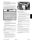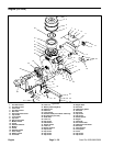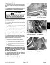
Engine Removal (Fig. 43)
1. Park machine on a level surface, lower attachment,
stop engine, engage, and remove key from the ignition
switch.
2. Chock wheels to prevent the machine from moving.
The brake assembly will be partially disassembled.
CAUTION
avoid possible burns, allow engine and exhaust
The muffler and exhaust pipe may be hot. To
system to cool before working near muffler.
3. Remove attachment from the rear of the machine to
gain access to the engine.
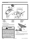
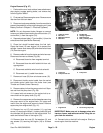
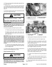
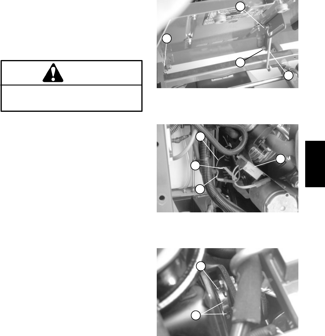
4. Pivot seat up. Remove seat base with seat attached
as follows (Fig. 44):
A. Separate seat rod from the base by removing
cotter pin and flat washer.
B. Separate base from frame by removing both lock
nuts, cap screws, flat washers, and spacers.
5. Disconnect and remove battery from the machine to
prevent the possibility of the engine damaging it during
removal (see Battery Service in Chapter 5 – Electrical
Systems).
6. Close fuel shutoff valve. Clamp fuel hose near engi-
ne to prevent fuel spillage. Loosen hose clamp at fuel
pump and remove fuel hose from the pump.
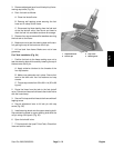
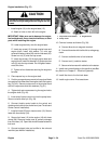
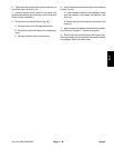
7. Disconnect wire harness as follows (Fig. 45):
A. Disconnect blue wire from magneto terminal.
B. Disconnect blue wire with fusible link from volt-
age regulator.
C. Disconnect red/white wire from fuel solenoid.
IMPORTANT: Keep air cleaner base removed from
the carburetor after disconnecting the choke cable
from the choke lever. This is necessary to remove
the engine from the machine.
8. Disconnect throttle control cable from the swivel
and choke control cable from the choke lever (see
Throttle and Choke Control Removal).
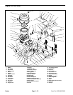
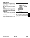
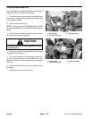
9. Loosen both set screws on the engine hub to re-
move hub from the engine shaft (Fig. 46).
3
2
4
1
Figure 44
1. Cotter pin & flat washer 3. Lock nut
2. Seat rod 4. Cap screw & flat washer
1
2
4
3
Figure 45
1. Blue wire (magneto) 3. Voltage regulator
2. Blue wire (voltage reg.) 4. Red/white wire
1
2
Figure 46
1. Set screw 2. Engine hub
Engine
Sand Pro 2020/3020/5020 Page 3 – 27 Engine


