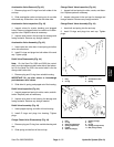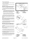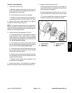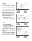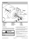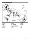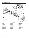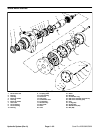
Removal (Fig. 57 or 55)
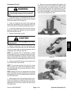
1. Before removing any parts from the hydraulic sys-
tem, park the machine on a level surface, lower attach-
ment, and stop the engine.
CAUTION
draulic oil. Controls must be operated with the
tion switch.
Operate all hydraulic controls to relieve system
pressure and avoid injury from pressurized hy-
ignition switch in OFF. Remove key from the igni-
WARNING
Before jacking up the machine, review and follow
Jacking Instructions in Chapter 1 – Safety.
2. Jack up rear wheel and use wood blocks to keep the
rear tire off the floor.
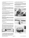
3. Remove lug nuts from drive studs. Pull wheel from
drive studs and wheel hub.
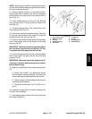
IMPORTANT: DO NOT hit wheel hub with a hammer
during removal. Hammering may cause damage to
the motor.
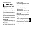
4. Apply parking brake. Remove lock nut from wheel
motor shaft. Release parking brake.
5. Use a puller to remove brake drum and wheel hub.
Remove woodruff key from the wheel motor shaft.
6. Remove retaining clip securing the cam shaft to the
brake lever. Separate lever from cam.
NOTE: The brake assembly consists of return spring,
brake cam, brake shoes, backing plate, and anchor pin.
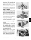
7. Remove brake assembly from the brake bracket by
removing four lock nuts and cap screws from the back
-
ing plate and brake bracket. Do not disassemble.
8. Clean wheel motor and hydraulic connections. La-
bel all connections for reassembly.
NOTE: The right wheel motor has an extra hydraulic
tube and fitting attached to it.
NOTE: On the SP 2020/3020, the hydraulic connec-
tions between the tubes and motor fittings are JIC con-
nections and use no O–rings.
9. Disconnect hydraulic tubes from the hydraulic fit-
tings. Allow tubes to drain into a suitable container.
10. Remove hydraulic fittings and O–rings from the
wheel motor. Put caps or plugs on disconnected tubes
and motor ports to prevent contamination from entering.
NOTE: On the SP 2020/3020, two hex nuts are used
with the top two cap screws when securing the wheel
motor to the frame.
11. Remove hex nuts, cap screws, spacers, and lock
washers securing the brake bracket and wheel motor to
the frame. Remove motor from the frame.
Installation (Fig. 57 or 56)
NOTE: On the SP 2020/3020, two hex nuts are used
with the top two cap screws when securing the wheel
motor to the frame.
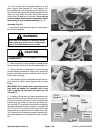
1. Position wheel motor to the frame. Secure motor
and brake bracket to the frame with four cap screws,
spacers, lock washers, and hex nuts.
2. Remove caps or plugs from the wheel motor. Lubri-
cate new O–rings with clean hydraulic fluid. Install O–
rings and hydraulic fittings to the motor and tighten.
NOTE: The right wheel motor has an extra hydraulic
tube and fitting attached to it.
NOTE: On the SP 2020/3020, the hydraulic connec-
tions between the tubes and motor fittings are JIC con-
nections and use no O–rings.
3. Install hydraulic tubes to the hydraulic fittings. Tight-
en tube connections.
NOTE: The brake assembly consists of return spring,
brake cam, brake shoes, backing plate, and retaining
clip.
4. Install brake assembly to the brake bracket by se-
curing the backing plate to the brake bracket with four
cap screws and lock nuts. Secure brake lever to the
brake cam with the retaining clip.
IMPORTANT: DO NOT hit wheel hub with a hammer
during installation. Hammering may cause damage
to the motor.
5. Install woodruff key to the wheel motor shaft. Slide
brake drum and hub onto the motor shaft.
6. Secure lock nut to the wheel motor shaft. Torque nut
from 250 to 400 ft–lb (34.6 to 55.3 kg–m).
7. Install rim to the drive studs. Secure rim with lug
nuts. Torque nuts from 40 to 50 ft–lb (5.5 to 6.9 kg–m).
8. Charge hydraulic system (see Charge Hydraulic
System).
Hydraulic
Systems
Sand Pro 2020/3020/5020 Page 4 – 59 Hydraulic System (Rev. A)


