Sand Pro 2020/3020/5020Page 5 – 14Electrical Systems
Battery Service
The battery is the heart of the electrical system. With
regular and proper service, battery life can be extend.
Additionally, battery and electrical component failure
can be prevented.
CAUTION
When working with batteries, use extreme cau-
tion to avoid slashing or spilling electrolyte.
Electrolyte can destroy clothing and burn skin or
eyes. Always wear safety goggles and a face
shield when working with batteries.
Electrolyte Specific Gravity
Fully charged: 1.265 corrected to 80_F (26.7_C)
Discharged: less than 1.240
Battery Specifications
BCI Group Size UI:
280 CCA at 0_ F (–17.8_ C)
Reserve Capacity of 43 minutes at 25 amp and at
80_F (26.7_C)
Dimensions (not including terminal posts and caps)
Length 7.72 inches (19.60 cm)
Width 4.98 inches (12.65 cm)
Height 6.16 inches (15.65 cm)
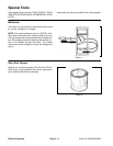
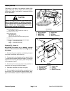
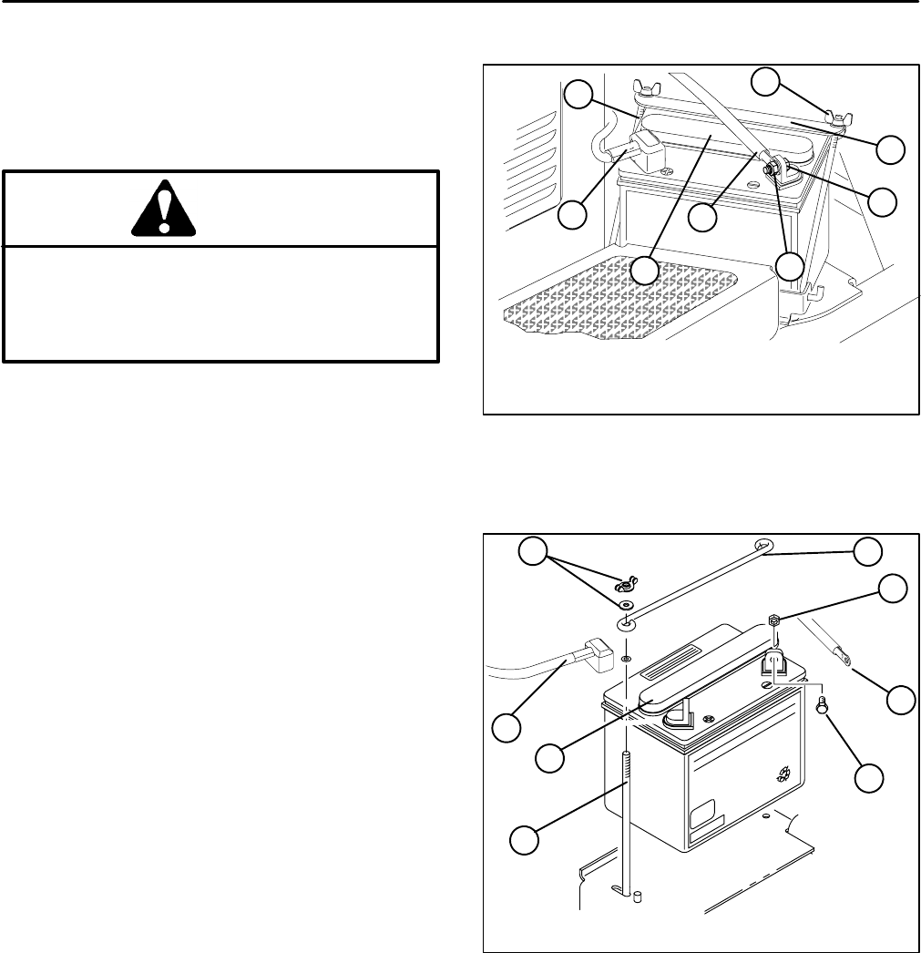
Removal (Fig. 10 and 11)
IMPORTANT: Be careful not to damage terminal
posts or cable connectors when removing the bat-
tery cables.
1. Remove wing nuts, washers, and battery clamp or
hold down from battery hold down rod.
2. Remove lock nut and cap screw from ground cable
(–) post first and remove cable from battery. This should
prevent short circuiting the battery, other components,
or the operators hands.
3. Remove lock nut and cap screw from positive (+)
cable post and remove cable from battery.
4. Make sure manifold vent cap is on tightly.
5. Remove battery from the battery compartment to a
service area. This will minimize possible battery dam-
age and allow better access for inspection and service.
Figure 10
1. Wing nut & washer
2. Hold down rod
3. Battery clamp
4. Negative cable
5. Positive cable
6. Lock nut
7. Cap screw
8. Manifold vented cap
1
6
5
4
2
3
7
8
SP 2020/3020
Figure 11
1
3
2
5
6
4
7
1. Wing nut & washer
2. Hold down rod
3. Battery hold down
4. Negative cable
5. Positive cable
6. Lock nut
7. Cap screw
8. Manifold vented cap
8
SP 5020


