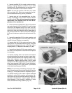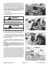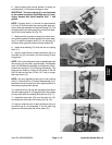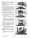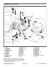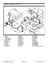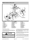
Removal (Fig. 87)
1. Before removing any parts from the hydraulic sys-
tem, park machine on a level surface, set brake, lower
attachment, and stop engine.
CAUTION
draulic oil. Controls must be operated with the
tion switch.
Operate all hydraulic controls to relieve system
pressure and avoid injury from pressurized hy-
ignition switch in OFF. Remove key from the igni-
2. Pivot seat up. Remove cover (8) from the midsec-
tion of the machine.
3. Disconnect air hose attached to the air cleaner on
the engine.
4. Remove both lock nuts (12), cap screws (15), and
strip retainer (19) securing the lower part of the rubber
shield (20) to the frame. Position shield away from the
bottom of of the oil cooler (2).
5. Clean both 90
o
hydraulic fittings (5), hydraulic hose
(43), and valve to cooler tube (6). Clean oil cooler (2) in
the area of these fittings.
6. Label all hydraulic connections for reassembly.
7. Place a suitable container under 90
o
hydraulic fitting
(5) at the bottom of the oil cooler (2) to collect hydraulic
oil.
8. Disconnect valve to cooler tube (6) from 90
o
hydrau-
lic fitting (5). Allow fluid to drain from into the container.
9. Disconnect hydraulic hose (43) from 90
o
hydraulic
fitting (5). Allow fluid to drain completely from the cooler
into a suitable container.
10. Put caps or plugs on disconnected hoses and fit-
tings to prevent contamination.
11. Remove both cap screws (11), spacers (16), and flat
washers (17) from rubber clamps (3) and T–nuts (4).
12. Pull the oil cooler (2) from the machine.
13. Remove 90
o
hydraulic fittings (5) and O–rings (29)
from the oil cooler (2).
Cleaning and Inspection (Fig. 87)
1. Back flush oil cooler with cleaning solvent (bottom
opening to top opening). After cooler is clean, make sure
all solvent is drained from the cooler.
CAUTION
Use eye protection such as goggles when using
compressed air.
2. Dry inside of oil cooler using compressed air in the
opposite direction of the oil flow (bottom opening to top
opening).
3. Plug both ends of the oil cooler. Clean exterior of the
cooler. Make sure fins are clear of dirt and debris.
4. The oil cooler should be free of corrosion, cracked
tubes, and excessive pitting of tubes.
Installation (Fig. 87)
1. Make sure hydraulic both openings to the oil cooler
are clean. Remove plugs from the cooler openings.
2. Reinstall O–rings (29) and 90
o
hydraulic fittings (5)
to the oil cooler (2).
3. Position the oil cooler (2) to the front shield (26).
4. Secure oil cooler to the front shield (26) with both
rubber clamps (3), flat washers (17), spacers (16), cap
screws (11), and T–nuts (4).
5. Remove caps or plugs on disconnected hoses and
fittings.
6. Reconnect valve to cooler tube (6) to 90
o
hydraulic
fitting (5).
7. Reconnect hydraulic hose (43) to 90
o
hydraulic fit-
ting (5).
8. Reinstall cover (8) to the midsection of the machine.
Pivot seat down.
9. Fill tank with hydraulic fluid (see Check Hydraulic
System Fluid and Change Hydraulic System Oil and Fil
-
ter).
10. Charge hydraulic system (see Charge Hydraulic
System).
Hydraulic
Systems
Sand Pro 2020/3020/5020 Page 4 – 73 Hydraulic System (Rev. A)


