


Electrical Installation Instructions
For Connection to 240V Service
IMPORTANT
NOTICE: The electrical wiring of this hot tub must meet the
requirements of the National Electrical Code (NEC) and any applicable state
or local codes. The electrical circuit must be installed by a qualified electri-
cian and approved by a local building/electrical inspection authority.
1. This hot tub must be permanently connected (hard-wired) to the power
supply. No plug-in connections or extension cords are to be used in
conjunction with the operation of this hot tub. Supplying power to
the hot tub which is not in accordance with these instructions will void
both the independent testing agency listing and the manufacturer’s war-
ranty.
2. The power supplied to this hot tub must be a dedicated circuit with no
other appliances or lights sharing the power provided by the circuit.
3. To determine the current, voltage and wire size required, refer to the
power supply table on page 12.
– Wire size must be appropriate per NEC and/or local codes.
– We recommend type THHN wire.
– All wiring must be copper to ensure proper connections. Do not use
aluminum wire.
– When using wire larger than #6, add a junction box near the hot tub
and reduce to short lengths of #6 wire to connect to the hot tub.
4. The electrical supply for this product must include a suitably rated switch
or circuit breaker to open all ungrounded supply conductors to comply
with Section 422-20 of the National Electrical Code, ANSI/NFPA 70. The
disconnecting means must be readily accessible to the hot tub’s occupant
but installed at least 5 feet (1.5m) from hot tub water.
5. The electrical circuit supplied for the hot tub must include a suitable
ground fault circuit interruptor (GFCI) as required by NEC Article 680-42.
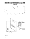
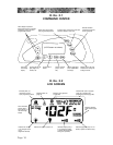
6. To gain access to the hot tub’s power terminal block, remove the four
screws securing the center cabinet panel on the side of the hot tub under
the controls. Then open the door to the control box. (Ill. No. 1, item 1).
7. Select the power supply inlet you want to use (Ill. No. 1, item 2) and
remove the short cabinet panel from the front of the hot tub to allow you
to feed the cable through to the control box. Install the cable with con-
nector through the large opening provided in the bottom of the control
box.
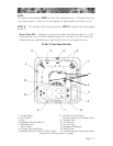
8. Connect wires, color to color, on terminal blocks TB1 and TB3 (Ill. 1.2).
TIGHTEN SECURELY! All wires must be hooked up or damage could
result.
9. Close the control box door and reinstall the cabinet side panels.
Page 11