


23
Section 3 - OPERATING INSTRUCTIONSSection 5 - ADJUSTMENTS & REPAIR
5.3 TRACTION BELT TENSION
The traction drive belt tension does not require adjustment.
If the belts are slipping, they will have to be replaced.
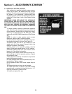
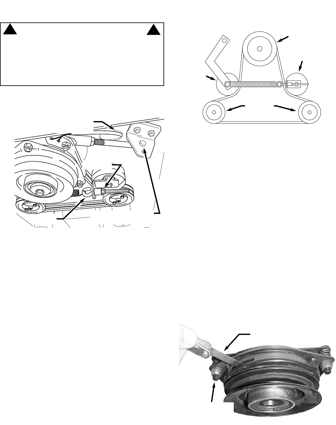
5.4 TRACTION BELT REPLACEMENT
1. Remove clutch to deck belt. Refer to Section
“Mower Drive Belt Replacement”.
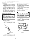
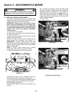
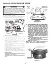
2. Turn hex nuts out to the end of eyebolt, reducing
spring tension. See Figure 5.9.
3. Remove hardware securing anti-rotation bracket to
frame. See Figure 5.9. NOTE: Do not remove anti-
rotation bracket from clutch.
4. Disconnect the electric clutch from main wire har-
ness. See Figure 5.9.
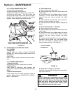
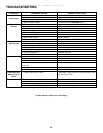
5. Remove traction belts from around engine pulley
and hydro pumps.
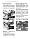
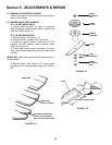
6. Install new belts, routing around engine pulley and
hydro pump pulleys. See Figure 5.10.
7. Reconnect electric clutch to main wire harness.
8. Reinstall anti-rotation bracket to frame and tighten
hardware securely.
9. Run hex nuts all the way to the end of the threads
on the eyebolt. See Figure 5.9.
10. Reinstall electric clutch to deck belt onto electric
clutch.
FIGURE 5.9
WARNING
DO NOT attempt any maintenance, adjustments or
service with engine running. STOP engine. STOP
blades. Set brake. Remove key. Remove spark plug
wires and secure away from spark plugs. Engine and
components are HOT. Avoid serious burns, allow suf-
ficient time for all parts to cool.
!
!
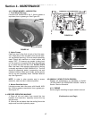
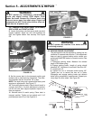
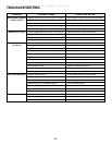
FIGURE 5.11
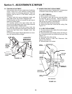
INSERT FEELER GAUGE.
GAP SHOULD BE .015
ROTATE NUTS IN OR
OUT TO ACHIEVE
CORRECT GAP
5.5 BLADE BRAKE/ELECTRIC CLUTCH ADJUSTMENT
The blade switch engages the electric clutch when
pulled out to the "ON" position. When the blade switch
is in the "ON" position the cutting blade(s) are
engaged. The blade switch disengages the electric
clutch when the blade switch is pushed in to the "OFF"
position. When the blade switch is in the "OFF" posi-
tion the cutting blade(s) are disengaged. The electric
clutch is adjustable. The blades should stop rotation in
7 seconds or less. If the electric clutch fails to stop the
blades rotation in 7 seconds, adjustment is necessary.
1. Insert a feeler gauge into the three slots on the
electric clutch.
2. Check gap through all three slots in the side of the
clutch. The gap should be set at .015.
3. If gap is incorrect rotate nuts in or out to achieve the
correct gap. See Figure 5.11.
NOTE: Electric Clutch is shown removed from the
machine. Removal is not necessary for adjustment.
FIGURE 5.10
(View looking up)
ENGINE PULLEY
(ABOVE CLUTCH)
STATIONARY
IDLER
TENSIONING
IDLER
PUMP
PULLEYS
TRACTION
BELT
ROUTING
HEX NUTS
REMOVE ANTI-ROTATION
BRACKET FROM FRAME
DISCONNECT CLUTCH FROM
MAIN WIRING HARNESS
EYEBOLT