


21
Section 3 - OPERATING INSTRUCTIONSSection 5 - ADJUSTMENTS & REPAIR
5.1 NEUTRAL POSITION ADJUSTMENTS
(Continued From Previous Page)
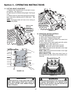
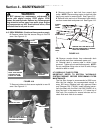
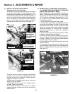
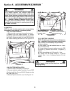
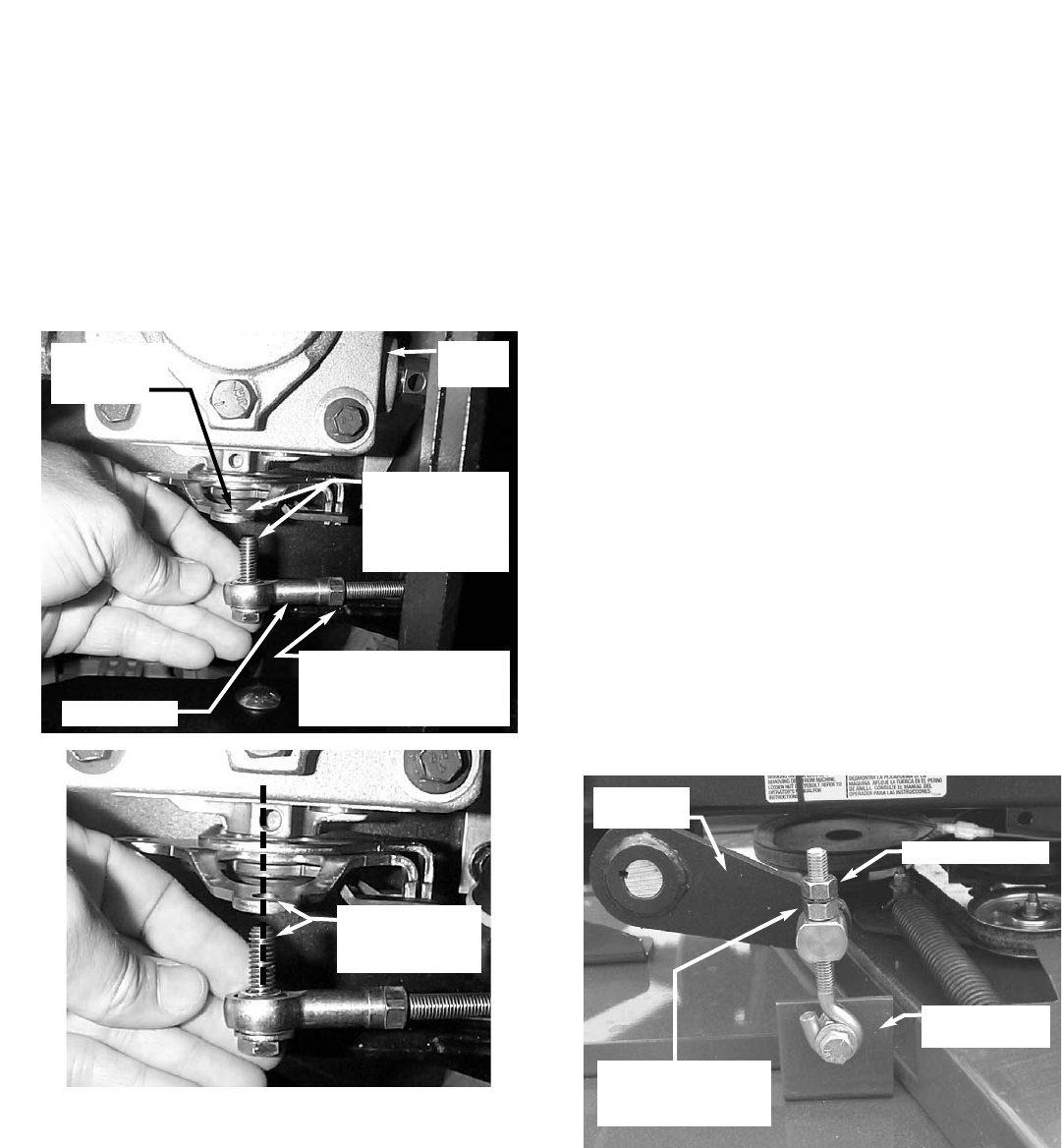
12. With motion control levers remaining in the neutral
lock position, See Figure 3.7, hold connecting rod up
to the activation assembly and check length of rod. Tie
rod end bolt must align with the activation assembly. If
bolt is not aligned with the activation assembly, adjust
tie rod. Loosen jam nut that secures tie rod. Rotate tie
rod in or out to align with hole in activation assembly.
Repeat step for other hydro pump. See Figure 5.4.
13. Once tie rod end bolt is aligned with activation
assembly insert into hole and reinstall washers and
nut that secure bolt to assembly. Tighten securely.
Tighten tie rod jam nut securely.
14. Start engine, disengage parking brake, and check
rotation of the rear wheels.
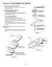
15. Reinstall both hydro pump fans. Reinstall washer
and bolt. Tighten bolt securely.
16. Reinstall pump fan cover plate and tighten
hardware securely. Replace any fuel line wire ties that
were removed.
5.2 MOWER DECK & COMPONENT ADJUSTMENTS
5.2.1. MOWER DECK ADJUSTMENT (LEVELNESS)
SIDE to SIDE and FRONT to REAR
Before making deck leveling adjustments, inflate rear
tires to 12 PSI and front tires to 25 PSI. When adjust-
ed correctly, the deck will be level side to side within
1/8”, have a low cut setting of approximately 1” (1 1/4"
for 61 deck) and the blades pitched approximately
3/16” higher at the rear.
1. Place machine on a smooth level surface.
2. Check side to side level by rotating blades until tips
are pointing to the sides of the deck. Check the meas-
urement of outside blade tips to the ground on both
blades. The measurement of each of the outside blade
tips should be within 1/8” of each other. If measure-
ment of the blade tips is not within 1/8”, adjustment
should be made.
3. Set the mower deck to the transport position. Refer
to Section “Cutting Height Adjustment”.
4. Relieve tension on deck lift assist spring by loosen-
ing nut on eyebolt. Refer to Section “Removing Deck”.
5. Place 1” blocks (1 1/4" for 61 deck) under the front
and rear edge of the mower deck.
6. Insert stop pin into lowest cutting height, and lower
deck onto blocks.
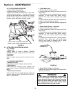
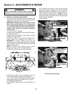
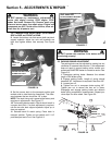
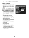
7. Loosen the top nuts that secure both front deck
support eyebolts. Adjust bottom nuts until eyebolts are
tight, then retighten top nuts. Torque to 20 to 30 ft. lbs.
See Figure 5.5.
FIGURE 5.4
HYDRO PUMP
ACTIVATION
ASSEMBLY
TIE ROD END
BOLT IS SHOWN
MISALIGNED
WITH ACTIVATION
ASSEMBLY
BOLT IS SHOWN
ALIGNED WITH
HOLE
HYDRO
PUMP
LOOSEN NUT AND
ROTATE TIE ROD END IN
OR OUT TO ALIGN WITH
ACTIVATION ASSEMBLY
TIE ROD END
DECK HANGER
BRACKET
FIGURE 5.5
LOOSEN TOP NUT
FRONT
LIFT ARM
ADJUST BOTTOM
NUT UNTIL EYEBOLT
IS TIGHT