


20
Section 3 - OPERATING INSTRUCTIONS
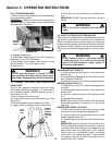
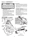
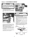
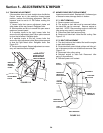
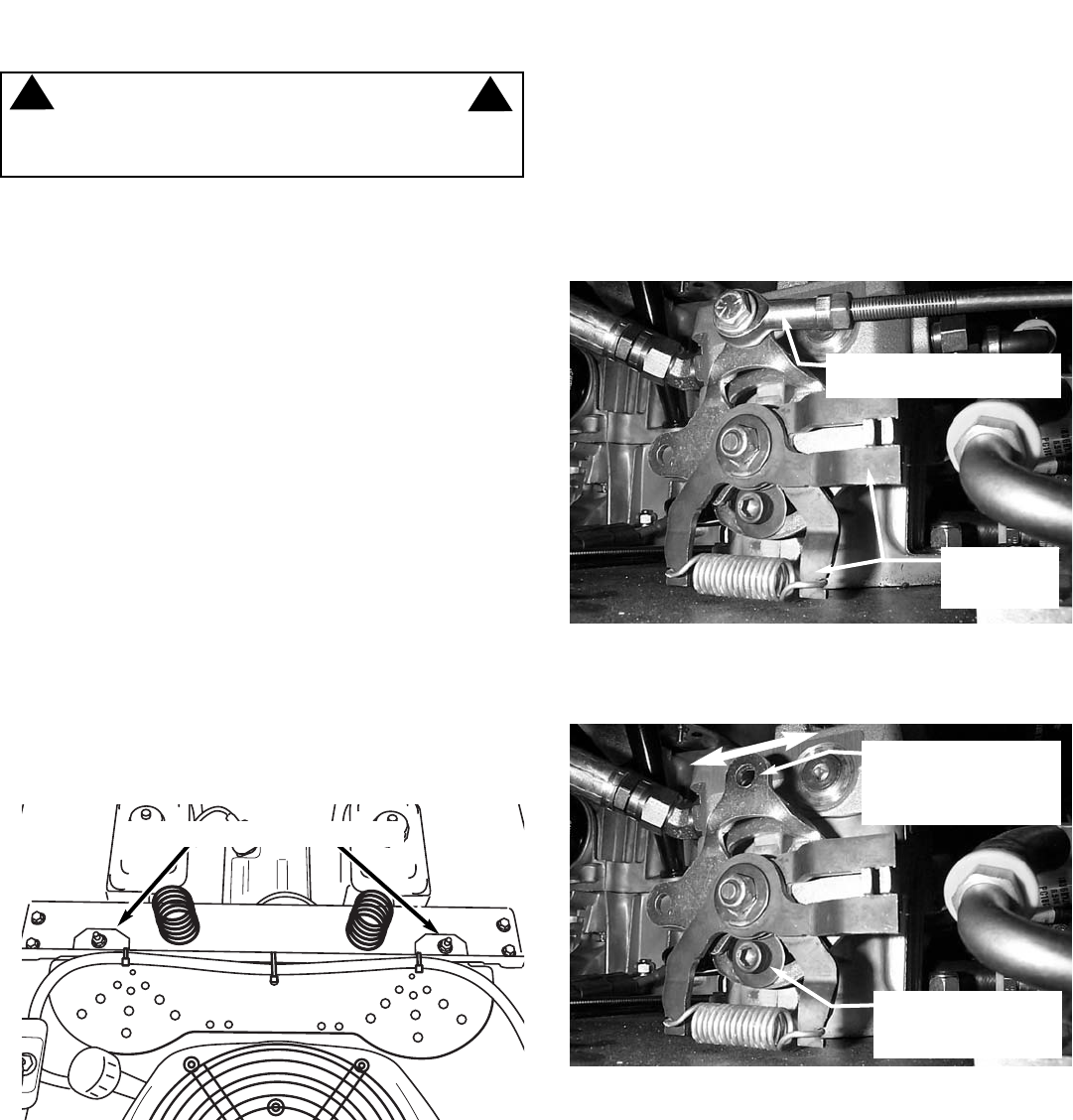
10. If wheel(s) are rotating, loosen the hydro pump
activation assembly retaining screw. Move activation
assembly forward or rearward to stop rotation of
wheel. Retighten retaining screw. Repeat this step for
other hydro pump. See Figure 5.3. NOTE: On some
pumps, the retaining screw is located on the upper half
of the activation assembly.
11. Stop engine.
Section 5 - ADJUSTMENTS & REPAIR
5.1 NEUTRAL POSITION ADJUSTMENTS
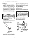
The motion control levers control the movement and
stopping of the machine. Move the control levers to the
center or neutral position to stop machine.
IMPORTANT: Always return both motion control
levers with hand assistance to the neutral posi-
tion. If machine does not come to a complete stop
or machine has movement when control levers are
moved to the neutral lock position, adjustment
must be made.
1. Turn key to "OFF" position.
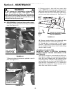
2. Move motion control levers to the neutral lock posi-
tion. Refer to Figure 3.7.
3. Raise both rear wheels off the ground. Secure
machine with safety blocks.
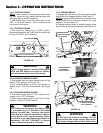
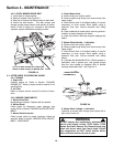
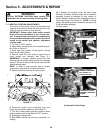
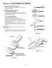
4. Remove pump fan cover plate to expose top of
hydro pumps and linkages. See Figure 5.1.
IMPORTANT: If needed, carefully remove wire ties
securing fuel line to plate, being careful not to damage
fuel line. Be sure to secure fuel line with new wire ties
after reinstalling plate.
NOTE: In order to raise operator seat to access
components, seat must be in rearmost position.
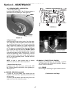
5. Remove both fans from top of hydro pumps.
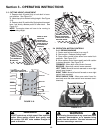
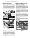
6. Disconnect motion lever connecting rods from
hydro pump activation assembly. See Figure 5.2.
7. Turn key to start position and start machine. Move
engine speed control to the Rabbit "FAST" position.
8. Disengage parking brake.
9. Both wheels should not have any movement, not
rotating.
FIGURE 5.2
HYDRO PUMP
ACTIVATION
ASSEMBLY
REMOVE MOTION CONTROL
LEVER CONNECTING ROD
FIGURE 5.3
LOOSEN ACTIVATION
ASSEMBLY RETAINING
SCREW
WARNING
Exercise EXTREME CAUTION when making this
adjustment, due to close proximity of moving parts.
!
!
(Continued On Next Page)
MOVE ACTIVATION
ASSEMBLY REARWARD
OR FORWARD TO
ACHIEVE NEUTRAL
FIGURE 5.1
REMOVE HARDWARE AND PLATE