


24
Lift Variations When Using Attachments
A
F
C
D
G
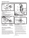
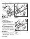
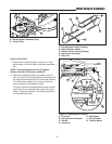
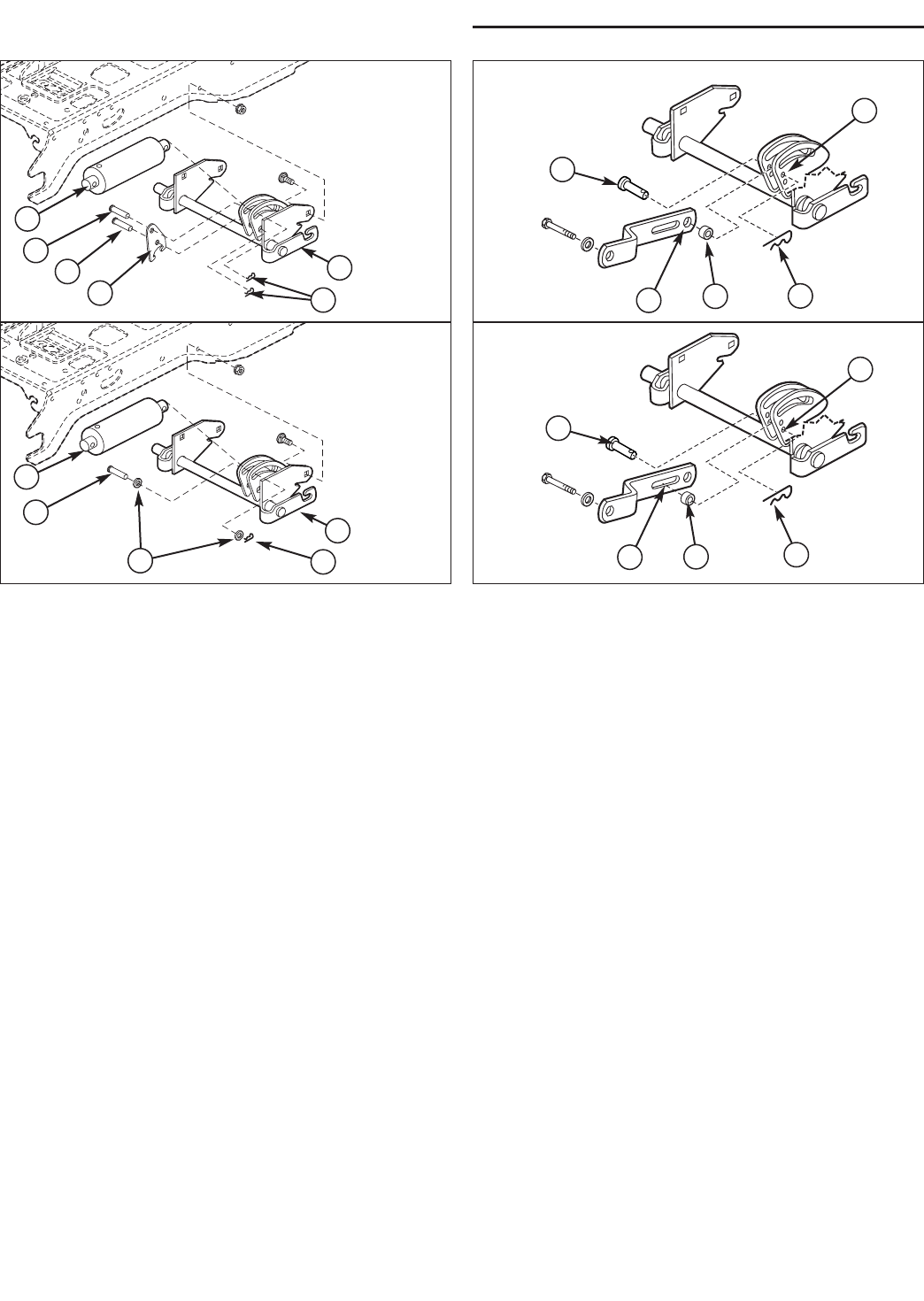
Figure 37. Lift Link - Manual Lift Models
A. Pin
B. Rear Hole of Lift Bar
(Snowthrower & Dozer Applications)
C. Spacer
D. Hair Pin Clip
E. Upper Hole (Snowthrower & Dozer Applications)
F. Slot of Lift Link (Mower Applications)
G. Lower Hole (Mower Applications)
A
B
C
D
E
Snowthrower
& Dozer
Applications
Mower
Applications
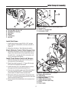
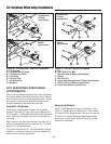
Figure 36. Lift Lock Plate - Hydraulic Lift Models
A. Lift Cylinder
B. Flat Head Pin (Original)
C. Flat Head Pin (New)
D. Lock Plate
E. Hair Pin Clips
F. Lift Shaft Assy.
G. Washers
A
B
C
D
F
E
A
B
F
G
E
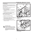
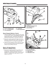
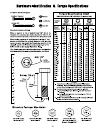
LIFT VARIATIONS WHEN USING
ATTACHMENTS
When a front-mounted attachment such as a snowthrow-
er or dozer blade is used with the tractor, the lift mecha-
nism must be locked to provide downward force. When
the mower is reinstalled the downward pressure lock
must be released so that the mower can float.
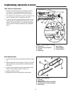
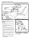
Hydraulic Lift Models
When using a snowthrower or dozer, the downward
pressure lock plate (D, Figure 36) and an additional pin
(C) is installed. These parts are included with the attach-
ment. Note that the washers (G) are not used with the
lock plate.
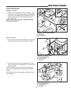
When mowing, the downward pressure lock plate (D) is
removed and replaced with two washers (G). The addi-
tional pin (C) is also removed.
Fully lower the hydraulic lift. The lift assembly is spring
loaded so it will need to be held in the down position to
perform of the following procedures.
Manual Lift Models
NOTE: These instructions apply to Conquest / 1700 /
2700 / YT Series tractors or Broadmoor / 1600 / 2600 /
LT Series tractors equipped with a lift lever kit 1694148.
The lift link is installed differently depending on what
attachment is being used. Refer to Figure 37 for link
installation information.
Snowthrower
& Dozer
Applications
Mower
Applications