


16
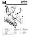
Initial Setup & Assembly
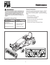
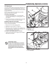
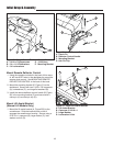
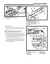
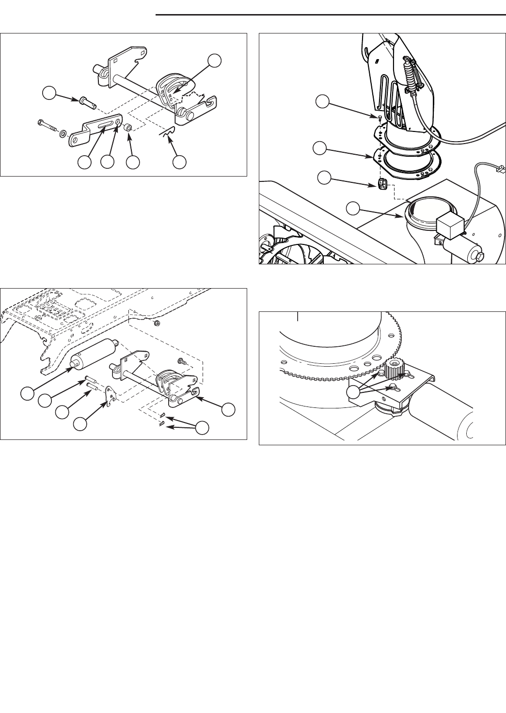
Figure 16. Assemble Discharge Chute
A. Plastite Screw C. Chute Ring
B. Hold-Down D. Reinforcement Ring Gear
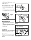
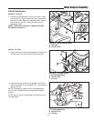
Figure 17. Discharge Chute Motor Adjustment
A. Adjustment Screws
A
B
C
D
INITIAL SETUP & ASSEMBLY
NOTE: Some of the following setup procedures may
already be completed.
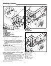
Install Hitch
Install the sub-frame hitch. Refer to sub-frame hitch
installation instructions for hitch modifications and 2-
stage snowthrower drive belt installation for Conquest /
1700 / 2700 / GT and Lift Lever Kit 1694148. Note that
the lift bar (B, Figure 14, manual lift models) or lock plate
(D, Figure 15, hydraulic lift models) must be placed in the
snowthrowing position (see page 22).
A
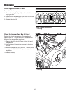
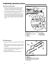
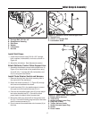
Figure 15. Install Lock Plate - Hydraulic Lift Models
A. Lift Cylinder D. Lock Plate
B. Flat Head Pin (Original) E. Hair Pin Clips
C. Flat Head Pin (New) F. Lift Shaft Assy.
A
B
C
D
F
E
A
B
C
D
E
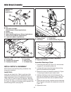
Figure 14. Connect Lift Link - Manual Lift Models
A. Pin
B. Rear Hole of Lift Bar
(Snowthrower & Dozer Applications)
C. Spacer
D. Hair Pin Clip
E. Upper Hole (Snowthrower & Dozer Applications)
F. Slot of Lift Link (Mower Applications)
G. Lower Hole (Mower Applications)
Snowthrower
& Dozer
Applications
Assemble Discharge Chute
1. Locate the hold downs (B, Figure 16), reinforcement
ring gear (D), and plastite screws (A).
2. Lubricate the base of the discharge chute and ring
gear with automotive lithium grease.
3. Remove the cover and loosen the screws (A, Figure
17) securing the electric spout rotator motor.
4. Install the discharge chute and reinforcement ring
gear (D), and secure to the chute ring (C, Figure 16)
using the three hold downs (B) and plastite screws
(A).
5. Adjust the motor so that it meshes with the discharge
chute ring gear and tighten the adjustment screws (A,
Figure 17).
6. Replace the cover.
F