


23
Removing & Installing the Snowthrower
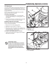
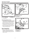
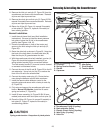
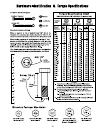
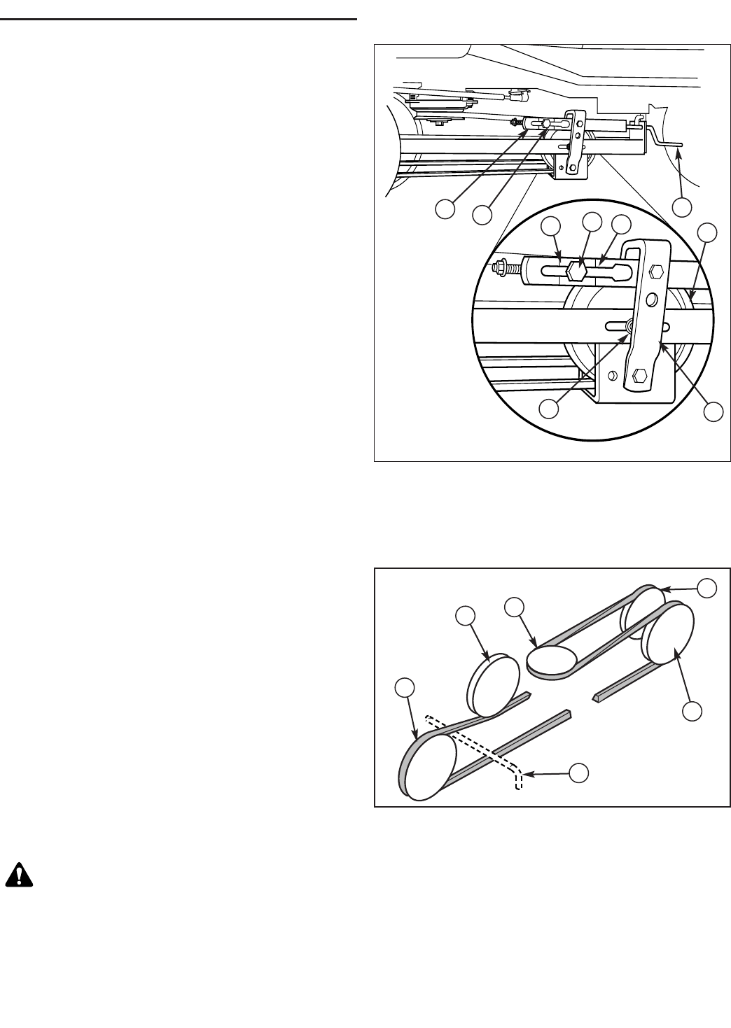
Figure 34. Adjusting Belt Tension
A. Trunnion E. Idler Pulley
B. Spring Tension Bracket F. Pivot Bracket
C. Handle G. Tension Marks
D. Capscrew
A
C
E
F
B
G
G
A
D
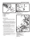
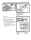
8. Remove the hitch pin and clip (D, Figure 33) from the
snowthrower and remove the snowthrower. Reinstall
all pins and clips to prevent loss.
9. Remove the clevis pin and hair pin (G, Figure 33 RH
manual lift models) frame mounted bracket. Reinstall
all pins and clips to prevent loss.
10.Return the lift bar (B, Figure 14, manual lift models)
or lock plate (D, Figure 15, hydraulic lift models) to
lawn mowing position.
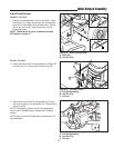
Normal Installation
1. Install the sub-frame hitch (see Hitch Installation
Instructions). Be sure to install the down pressure
lock plate or place the lift link in the snowthrower
position (see Figures 14 & 15).
2. Place the snowthrower in front of the tractor and
secure to the hitch using the hitch pin and clip (D,
Figure 33).
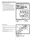
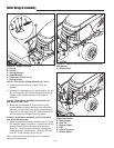
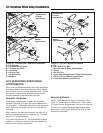
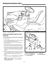
3. Route the drive belt as shown in Figure 35. Note that
the back of the belt rides in the back-side idler (B).
Note that the pin (E) goes between the belt.
4. With the snowthrower drive belt installed, trunnion (A,
Figure 34) should be between the marks (G) on
spring tension bracket (B) for correct belt tension.
Turn belt tension handle (C) to move trunnion forward
or rearward until between marks.
5. Connect the rear of the lift rod (B, Figure 33) to the lift
arm extension. Use a hair pin clip (C) to secure the
front of the lift rod to the snowthrower.
6. Connect the rotator motor plug (A). Route the har-
ness along the deflector control cable as shown.
7. Install the remote chute deflector control to the
mounting plate and secure with a clevis pin and clip
(E, Figure 33).
8. Fully raise and support the snowthrower with wood
blocks. Manual Lift Models: Install the lift assist
spring and anchor (F, Figure 33).
9. Install lift lever assembly (H, Figure 33 RH lift lever
models) and secure with clevis pins and hair pins (G)
10.Place the lift bar (B, Figure 14, manual lift models) or
lock plate (D, Figure 15, hydraulic lift models) in
snowthrowing position.
CAUTION
Spring under tension. Keep clear of pinch points.
B
C
B
D
E
A
Figure 35. Belt Routing
A. Snowthrower Pulley (V-pulley)
B. Back-side Idler Pulley
C. Electric Clutch Pulley (V-pulley)
D. Idler Pulley (V-pulley)
E. Hitch Pin