


21
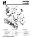
Initial Setup & Assembly
A
B
B
C
B
D
E
A
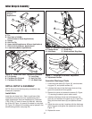
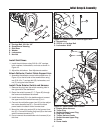
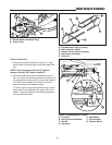
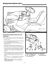
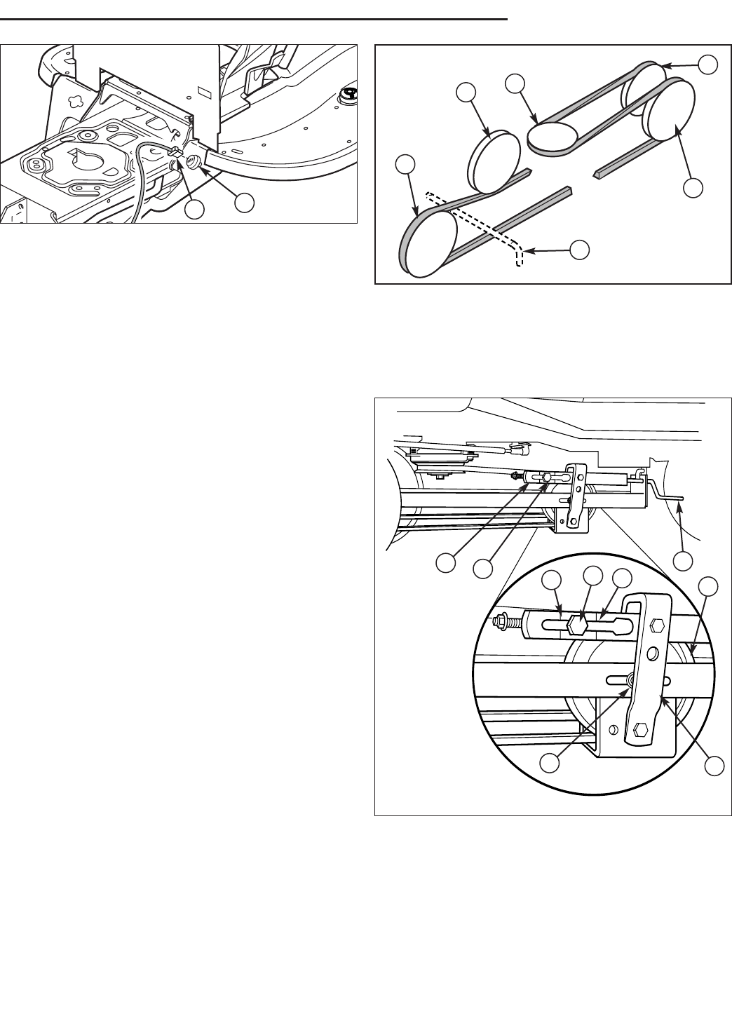
Figure 30. Rotator Motor Electrical Connection
A. Rotator Motor Harness & Plug
B. Tractor Plug
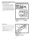
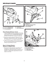
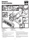
Figure 31. Belt Routing
A. Snowthrower Pulley (V-pulley)
B. Back-side Idler Pulley
C. Electric Clutch Pulley (V-pulley)
D. Idler Pulley (V-pulley)
E. Hitch Pin
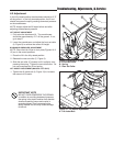
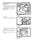
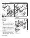
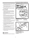
Figure 32. Adjusting Belt Tension
A. Trunnion E. Idler Pulley
B. Spring Tension Bracket F. Pivot Bracket
C. Handle G. Tension Marks
D. Capscrew
INSTALL DRIVE BELT
7. Route the drive belt as shown in Figure 31. Note
that the back of the belt rides in the back-side idlers
(B).
NOTE: The snowthrower hitch pin (E) goes in
between the belt, NOT below or above it.
8. With the snowthrower drive belt installed, the trun-
nion (A, Figure 32) should be between the marks (G)
on spring tension bracket (B) for correct belt tension.
Turn belt tension handle (C) to move trunnion for-
ward or rearward until between marks.
If trunnion cannot be placed between marks, loosen
capscrew (D) and reposition idler pulley (E) as nec-
essary. The pivot bracket (F) should be perpendicu-
lar to snowthrower hitch.
A
C
E
F
B
G
G
A
D