


17
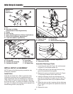
Initial Setup & Assembly
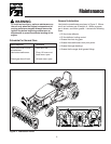
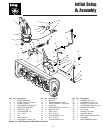
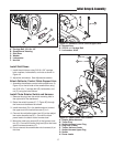
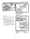
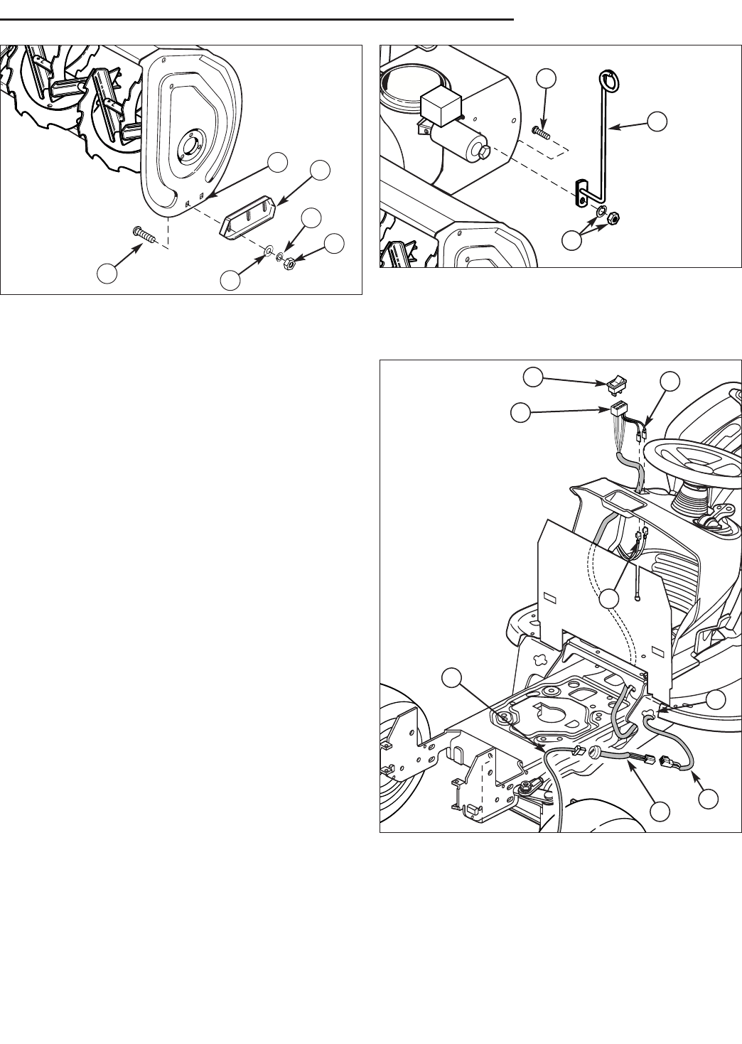
Figure 18. Skid Shoe Installation
A. Carriage Bolt, 3/8-16 x 3/4”
B. Snowthrower Housing
C. Skid Shoe
D. Washer
E. Lockwasher
F. Hex Nut
A
B
C
D
E
F
Install Skid Shoes
1. Install the skid shoes using 3/8-16 x 3/4” carriage
bolts, washers, lockwashers, and nuts as shown in
Figure 18.
2. Adjust the skid shoes. See Adjustments section.
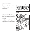
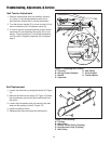
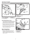
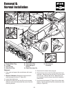
Attach Deflector Control Cable Support Arm
1. Assemble the deflector control cable support arm (A,
Figure 19) to the left side of the snowthrower using
one 5/16-18 x 1” carriage bolt (B), lockwasher, and
nut (C) using the holes shown.
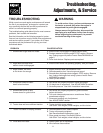
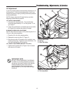
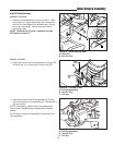
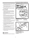
Install Chute Rotator Switch and Harness
1. Remove the plug from the switch mounting hole in
the right side of the dashboard.
2. Route the switch harness (C, F, Figure 20) through
the frame and dashboard as shown.
3. Install the switch (G) in the dashboard and connect
the upper end of the switch harness (F) to it.
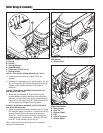
4. Connect the red/yellow power lead (H) to the red/yel-
low tractor harness lead (E). Connect the black
power lead to the black tractor harness lead.
5. Mount the trailer plug socket (B) in the frame at loca-
tion (D). Connect the trailer plug lead (B) to the lower
switch harness connector (C).
6. Do not connect the snowthrower wire harness (A) at
this time.
Figure 20. Install Power Port & Switch
A. Rotator Motor Harness
B. Trailer Plug
C. Switch Harness Lower Plug
D. Plug Hole (Frame)
E. Tractor Harness Leads
F. Switch Harness Upper Plug
G. Switch
H. Power Leads
G
A
B
F
H
E
C
D
B
A
Figure 19. Deflector Control Cable Support Arm
A. Support Arm
B. 5/16-18 x 1 Carriage Bolt
C. Lockwasher & Nut
C