


Assembly Section 3-7
ASSEMBLY
© 2004 Alamo Group Inc.
ASSEMBLY
Turf Flex 08/01
4
8
10
9
12
6
7
5
REAR
3
2
1
11
FIGURE 12
REAR
1
7
4
3
7
7
8
10
10
5
7
6
8
9
11
12
14
13
FIGURE 11
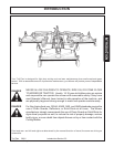
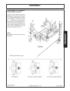
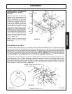
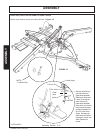
NOTE: Use Spacers #00763313,
1-3/8" long with Bolts.
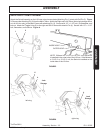
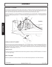
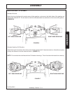
REAR MOWER ATTACHMENT
To install the Rear Attaching Arms (1) on the Main Frame to the Center Rear Mower: Note: These Arms are Right
and Left Hand. They must be installed with the chain attachment hole (11) to the top and the offset to the inside.
Remove the Click Pins and install Arms to the Rear Deck. Roll Mower into position and align the Attaching Arms
in Main Frame. Position the Rear Lift Frame on Main Frame. Note: Position the Rear Lift Frame with the 9/16"
dia. holes (12) facing to rear. Align with Lift Arm Pins (2) and install. ATTENTION: Do not drive pin in with hammer.
This will damage the PTFE Bearings which are installed in the Rear Attaching Arm (1). Pin should slide in with
very little resistance. Secure Pins with 1/2" x 1-1/2" bolts (3), flatwashers, and locknuts.
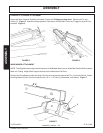
Install bushing in A-Frame Brace (4) and attach to the Rear Mower in the center hole of bracket on Gearbox mount
plate. Retain with 1/2" x 1-1/2" bolt, flatwasher, and locknut. Attach the A-Frame Link (5) to the Rear Lift Frame
by sandwiching between Toggle Links with Pins (6). Secure with 3/8" x 3" bolts (7), flatwashers, and locknuts.
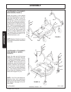
Attach the Lift Chain (8) to the Lift Arms and Rear Lift Frame. Attach the Rear Cylinder (9) to the Lift Frame with
Pin and Cotter Pin. Attach the Rear Lock-up Bar (10) to the Front Cylinder Pin, retain with cotter pin, and to the
Rear Cylinder Pin, retain with Clip Pin. Figure 12.
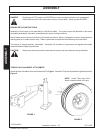
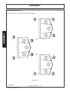
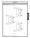
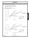
CASTER WHEEL ATTACHMENTS
WING MOWER (11' MODEL)
FIGURE 11
Attach the right and left Axle Arm
Weldment (1) to the outer deck with
3/8" Gr. 2 bolts (2) flatwasher (1-1/
2"OD x 3/16" thick) (3), and 3/8"
locknuts (4) in the front hole in Arm.
All other Arm retaining bolts are Gr.
5, 3/8" bolts. NOTE: Mount the
inside and out side wing arms in the
forward set of holes. Install four one
inch spacers (7) and two 1/4 inch
spacer (8) on each fork and wheel
assembly (9). Insert Wheel assem-
bly Shaft (9) into Axle Arm Weldment
(1) and retain with Snapper Pin (10).
The inside rear leg of the Wing Mow-
ers will require a height adjustment
shaft (11), spacer tube (12) and a
Spacer Pad (13) installed with a 3/8"
x 1-1/2" Screw (14).
NOTE: Spacer (13) rests on support
flat welded to front side of Mainframe
cross Tube.
R 12-14-95
5
2
3
4