


Assembly Section 3-6
ASSEMBLY
© 2004 Alamo Group Inc.
ASSEMBLY
Turf Flex 08/01
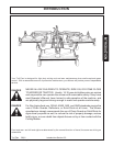
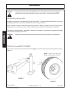
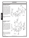
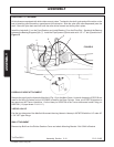
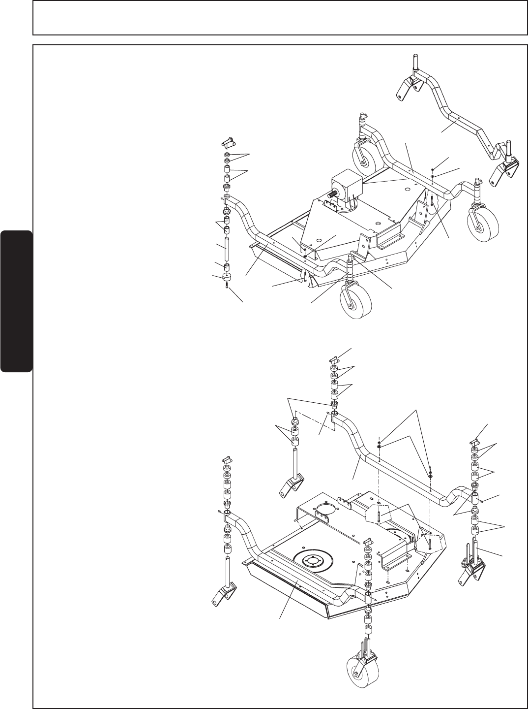
CASTER WHEEL ATTACHMENTS
REAR MOWER (11' MODEL)
FIGURE 10
Attach the right and left Axle Arm
Weldment (1) to the deck with 3/8"
Gr. 5 bolts (2) flatwasher (1-1/2"OD
x 3/16" thick) (3), and 3/8" locknuts
(4). NOTE: Mount the inside and
outside rear arms in the forward set
of holes. Install four one inch spac-
ers (7) and two 1/4 inch spacer (8)
on each fork and wheel assembly
(9). Insert Wheel assembly Shaft
(9) into Axle Arm Weldment (1) and
retain with Snapper Pin (10).
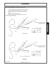
NOTE: Front Fork and Wheel As-
semblies have Lock mechanism
which will not allow wheel to caster
360 degrees. See page 3-5 for 48"
Deck detail.
1
1
2
10
6
7
5
7
8
9
6
10
8
7
7
5
4
3
FIGURE 10
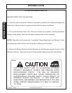
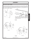
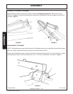
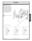
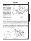
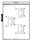
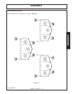
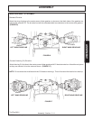
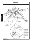
CASTER WHEEL ATTACHMENTS
WING MOWER (FIGURE 9)
Attach the inside (1) and outside
Axle Arm Weldments (1 or 1A) to the
outer deck with 3/8" Gr. 2 bolt (2),
flatwasher (1-1/2"OD x 3/16" thick)
(3), and 3/8" locknut (4) installed in
outer front hole. All other arm retain-
ing bolts are Gr. 5, 3/8" bolts (5). See
Fig. 13 & 14 for more details. Install
spacer (7,8,9) and forks as describe
in rear mower (Figure 8). The inside
rear leg of the wing mowers will
require a height adjustment shaft
(11), spacer tube (12) and a spacer
pad (13) installed with a 3/8" x 1 1/2"
socket head screw (14).
NOTE: Spacer (13) rests on support
flat welded to frontside of mainframe
cross tube.
5
4
3
10
2
1A
3
4
1
FIGURE 9
7,8,9
14
13
12
11
7
7
8
1
R 12-14-95