


6
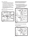
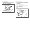
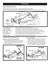
IDENTIFY YOUR SUSPENSION BRACKETS
• Compare your tractor to the illustrations shown below.
• If your tractor resembles the top illustration, proceed
to INSTRUCTIONS FOR TYPE A TRACTORS below.
• If your tractor resembles the bottom illustration,
proceed to INSTRUCTIONS FOR TYPE B
TRACTORS on page 7.
FRONT SUSPENSION
BRACKET
FRONT SUSPENSION
BRACKET
REMOVE BOLTS FROM THESE HOLES
FRONT
SUSPENSION
BRACKET
FIGURE 5
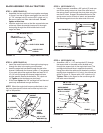
INSTRUCTIONS FOR TYPE A TRACTORS
STEP 1: (SEE FIGURE 5)
• Remove any bolts found in the holes indicated in the
illustration.
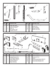
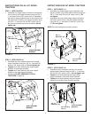
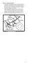
INSTRUCTIONS FOR TRACTORS WITH DUAL
FRONT DECK SUSPENSION BRACKETS
TYPE A
TYPE B
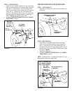
FIGURE 3
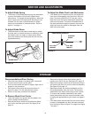
5/16" NYLOCK
NUT (K)
3/8" NYLOCK
NUT (L)
5/16" x 1" CARRIAGE
BOLT (F)
(SEE NOTE)
ENGINE
MOUNTING
PLATE
1/2" LARGE
WASHER (M)
3/8" x 1" CARRIAGE
BOLT (H)
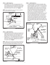
STEP 2: (SEE FIGURE 3)
• Fasten the R.H. Side Plate (bend facing out) to the
front three holes in the tractor frame using three 3/8"
x 1" carriage bolts (H), three large 1/2" washers (M)
(see note) and three 3/8" nylock nuts (L). For the
rear hole, use a 5/16" x 1" carriage bolt (F), a large
1/2" washer (M) and a 5/16" nylock nut (K). Place the
washers between the tractor frame and the side plate.
Tighten all bolts. Repeat for L.H. side plate.
• Reinstallthebrowningshieldremovedingure2.
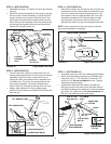
• Proceed to INSTRUCTIONS FOR ALL 917 MODEL
TRACTORS on page 8.
NOTE: If there is an engine mounting plate (shown with
dotted lines) leave the large 1/2" washer (M) off the bolt
that goes through the plate.
FIGURE 4