


11
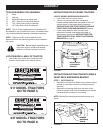
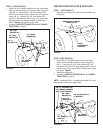
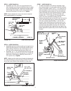
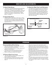
STEP 5: (SEE FIGURE 19)
• Assemble one 5/16" jam nut (I) approximately 3/4"
onto threaded end of control cable that has no rubber
cap or preassembled nuts. Assemble threaded cable
end through round hole in cable mount bracket and
secure with another 5/16" jam nut (I). Tighten.
NOTE: Some adjustment of jam nuts may be required
after blade assembly is completed.
CHANNEL ASSEMBLY
5/16" JAM
NUT (I)
5/16" JAM
NUT (I)
CABLE MOUNT
BRACKET
REAR
3/4"
FIGURE 19 (Left Hand Side View)
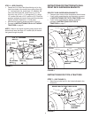
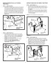
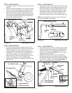
STEP 6: (SEE FIGURE 20)
• Assemble ball end of control cable up through hole in
cableendttingandpulluntilballslipsinsidecurled
edgeoftting.Ifballwon'tslipunderedgeofcurl,it
will need to be inserted through open end of curl.
• Assemble 1/4" x 1-1/2" (B) hex bolt down through the
cableendtting,the5/8"longspacer(T)andtheleft
hand hole in the channel assembly. Secure with a
1/4" nylock nut (J). Tighten.
NOTE: Make sure the cable mount bracket is aligned with
thecableendttingtopreventbindingofcable.Theother
end of the control cable will be attached in a later step.
FIGURE 20 (Left Hand Side View)
1/4" x 1-1/2"
HEX BOLT (B)
CABLE END
FITTING
1/4" NYLOCK NUT (J)
5/8" SPACER (T)
CHANNEL
ASSEMBLY
HOLE
REAR
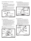
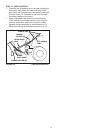
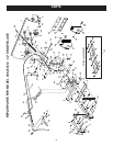
STEP 7: (SEE FIGURE 21)
• To attach the blade to the channel assembly, align
the notched holes in the pivot plate with the notched
holes in the blade. Insert a 1/8" x 1-1/4" cotter pin (P)
down through the hole at the bend in the blade pivot
shaft. Spread the ends of the pin. From the left side
insert the blade pivot shaft, bend facing top of blade,
through the notched holes. Secure the shaft with
another 1/8" x 1-1/4" cotter pin (P) through the end
hole in the shaft. Spread the ends of the pin.
• Remove the plastic cap and one 3/8" hex nut from the
bolt in the blade adjust spring. Adjust the remaining
3/8" hex nut down approximately 1" onto the bolt
threads. Hook the spring over the spring mount rod.
Place the bolt up through the hole in the top edge of
the blade and reassemble the other 3/8" hex nut to
the bolt and tighten down against the top edge of the
blade. Replace the plastic cap over the end of the bolt
threads.
(Right Hand Side View)
FIGURE 21
3/8" HEX NUT
(TOP)
PLASTIC
CAP
3/8" HEX NUT
(BOTTOM)
BLADE
1/8" x 1-1/4"
COTTER PIN (P)
BLADE
PIVOT
SHAFT
SPRING
MOUNT
ROD
BLADE
ADJUST
SPRING
1/8" x 1-1/4"
COTTER PIN (P)
PIVOT PLATE
NOTCHED HOLE