


12
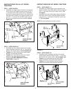
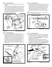
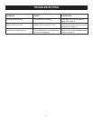
FIGURE 22 (Right Hand Side View)
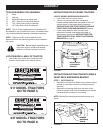
STEP 8: (SEE FIGURE 22)
• Assemble the large 1/2" washer (Q) onto the channel
pivot pin.
• Attach the channel assembly to the tractor by placing
the end of the channel assembly up inside the pivot
support bracket on the tractor. Align the hole in the
pivot support bracket with the second hole from the
end in the channel assembly. Insert the channel pivot
pin through the aligned holes from the left side and
secure with a hairpin cotter (O).
HAIRPIN
COTTER (O)
PIVOT SUPPORT
BRACKET
CHANNEL
PIVOT PIN
CHANNEL
ASSEMBLY
1/2" WASHER (Q)
CHANNEL
ASSEMBLY
HOLE
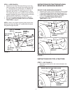
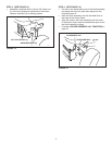
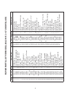
STEP 9: (SEE FIGURE 23)
• From the left side, insert the welded end of the lift
handle rod through the hole in the end of the channel
assembly (Figure 18). Next, insert the lift link pin
through the hole in the bracket that is welded to the
lift handle rod. (The lift link is pre-assembled to the
pivot support bracket). Secure the bracket with a
hairpin cotter (O) inserted up through the lift link pin.
• Apply a light coating of oil to the straight upper
portion of the lift handle rod. Slide the lift handle tube
onto the rod.
FIGURE 23 (Left Hand Side View)
LIFT HANDLE ROD
HAIRPIN COTTER (O)
LONG PIN
(LIFT LINK)
WELDED BRACKET
LIFT HANDLE TUBE
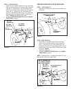
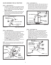
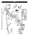
FIGURE 24 (Right Hand Side View)
STEP 10: (SEE FIGURE 24)
• Removetherubbercapandtherstjamnutfromthe
threaded end of the control cable and slide them onto
the control cable wire. Adjust the second jam nut on
the threads so that it is approximately 3/4" from end.
Assemble threaded end of cable through the cable
mountbracketandsecureitwiththerstjamnut.
Reinstall the rubber cap onto the threaded cable end.
NOTE: Some adjustment of jam nuts may be required
after blade assembly is completed.
RUBBER
CAP
CABLE MOUNT BRACKET
JAM NUTS
3/4"
CONTROL CABLE END
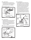
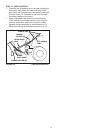
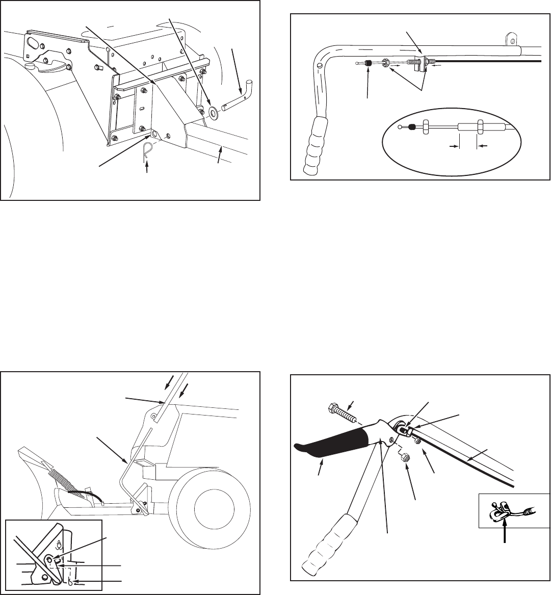
STEP 11: (SEE FIGURE 25)
• Assemble plastic grip onto lock release grip assembly.
• Attach lock release grip assembly to lift handle tube
using one 5/16" x 1-1/2" hex bolt (C) and one 5/16"
nylock nut (K). Do not overtighten the nut. The grip
assembly must pivot freely.
• Assemble the ball end of the cable to a cable end
ttingasyoudidtotheotherendofthecable.Secure
thecableendttingtotheweldboltonthelockrelease
grip with a 1/4" nylock nut (J). Do not overtighten the
locknut.Thecablettingmustpivotfreely.
FIGURE 25
(Right Hand Side View)
5/16" x 1-1/2"
HEX BOLT (C)
PLASTIC
GRIP
LOCK RELEASE
GRIP ASSEMBLY
1/4" WELD
BOLT
CABLE END
FITTING
5/16" NYLOCK
NUT (K)
1/4" NYLOCK
NUT (J)
CABLE
CABLE END
FITTING
CABLE END
FITTING