


ii
ASSEMBLY
i ii
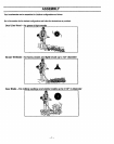
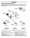
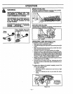
|RUSH TRI-BLADE CONFIGURATION BLADETRANSPORT/STORAGE COVER
_utting Line Head configuration is located before this
_-tien; Saw Blade configurationfollows this section.
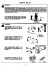
DANGER:
THE METAL BLADE SHIELD MUST BE
PROPERLY INSTALLED ON THE UNIT
ANYTIME THE UNIT IS USED WITH THE
BLADE. THE FORWARD TIP ON THE MET-
AL BLADE SHIELD HELPS TO REDUCE
THE OCCURRENCE OF BLADE THRUST
WHICH CAN CAUSE SERIOUS INJURY
SUCH AS AMPUTATION TO THE OPERA-
TOR OR BYSTANDERS.
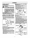
THE BLADES ARE SHARFAND'CAN cuT
YOU. BE SURE TO WEARGLOVES WHILE
WORKING WITH BLADES; '"
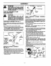
RE_;INSTALLATiON
the plastic linetrimmershield is installedon the unit,you
ust first remove the dualline cutting headbefore instal-
Ig the blade,,support flange, nut and metal blade shield.
Toremove (See Figure7), place lockingpinthrough the
gearbox and driving.'diskt0 prevent the arborshaftfrom
tumtng and remove the dual I|ne head byturning c_ock-
wise with blade nut/spark plug wrench. Save parts re-
moved for future use.
Remove 4 screws with hex key holdingthe plastic line
trimmer shield. Save these 4 screws for installationof
Ihe metal blade shield.
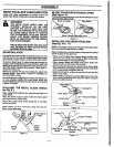
Fouhave already conliguredyour unitforSaw Blade use,
_u have already installed the metal blade sh=ieldand
rould remove thesaw b/adeand go directlyto Installing
e Bnisfi Tri-Blade:
ISTALUNG THE METAL BLADE SHIELD
lee Fig. 8 )
=lace met'a/blade s_hietdonme gearbo_cand_alignfour
_crew holes.
:_lacethe shield support plate L]ndeT.the_blade gua-_l _:
3rodalign the four,screw holes.
_ecure the metal blade shield using the 4 mounting
screws provided.
ghten evenly (70 Ib-in minimum) using hex key pro-
ded in loose parts bag.
Arbor
Shield Support
Metal
Driving
Disk Shield
Rgure 8
(1See Figure 9 )
e blade transport/storagecover shouldalways be used
when handlingeither blade.
Saw Blade
J
Blade TrensporVStorag_ Cover .
Figure 9
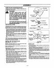
INSTALLING THE BRUSH "rRI-BLADE
..... 10& 11)
NOTE: The bladesin figures10 &11 are shownwithoutthe
blade transport/storagecover for clarity.
Before installing the brush tri-blade; makesure thedriving ':
diskis in place on the gear box.
• Place brush tfi-blade onto support flan0e making sure
the hole in the center of the blade is f'rttedaround the
raisedcenter stepon the support flange. :
• Place support flange and blade onto arbor shaft. The
blade should not move from side to side.
• Insert/ocking pin through the gearbox and driw'ngdls_
This will lockthe drivingdiskand prevent the arbor shall
from turning whileyou tighten the Rut.
• Begin threading the nut(counterclockwise) ontothe end
ofthe arbor shafL
•While holding loctdngp_nin place, tighten the nut onthe
arbor shaft counterclockwiseusing the blade nut/spark
plug wrench(20-35 Ib-ff).
Metal Blade\Nx.
Sh=eld__: Locking Pin
Arbor Shaft'-_'--_ _"
7_.,=-.-- Brush Tri-Blade
Driving Disk
Support_e._--- Nut
Flanqe
Figure 10
Locking Pin
Brush Tri-Blade
,_ Co_lockwise
_,_ __'_ _ _'Remove Clockwise
Metal Blade Blede N_'ut/Sp'_rkPlug
Shield Wrench
Figure 11
-9-