


i.i
ASSEMBLY
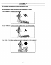
WARNING:
IF THIS UNIT IS RECEIVED
BLED, REVIEW ALL STEPS IN THIS
SECTION TO BE SURE ASSEMBLY
CORRECT AND
FORTHE OPERATOR.
HOW TO ASSEMBLE YOUR
BRUSHWACKER
DANGER:
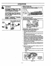
. Engineer,,/ ThrottleHandle
Screw_ Retention
Mounting'//// Clip
8r cket /
Figure 2
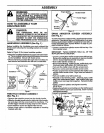
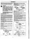
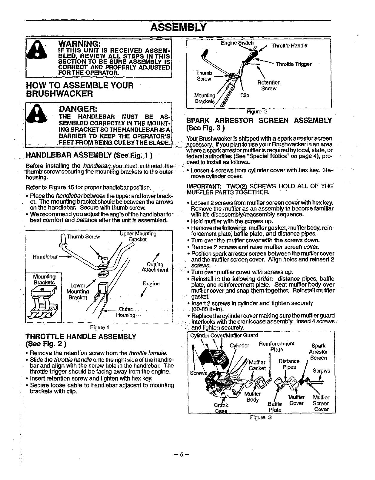
SPARK ARRESTOR SCREEN ASSEMBLY
(See Fig. 3 )
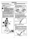
. BARRIER TO KEEP THE OPERATOR'S YourBrushwackerisshippedwith a spark arrestorscreen
..- FEETFROMB:Ir_._BITHEBLADE- _: '.acc_scry. fyouplantouseyourBrushwaskerinanarea
- . .......... Whe'maspark arrestormuffler is required bylocal state, or
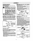
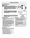
.....HANDLEBAR ASSEMBLY (See Fig. 1 ) " " federal authorities(See =Special Notice" on page 4), pro-
.............. ceed to nsta as fo owe.
uerore installing me nanolecar,:_you_-musLunmread:the_._. _". • - " .........
• thumbscrew securingthe mountingbracketsto the Outer • •.Loosen 4 screws rmm c_lnaer cover wJtnnex Key. He-. •
housing, movecylindercover.
Refer to Figure 15 for proper handlebar Position.
• Place the hand/ebarbetween theupperand lowerbrack-
eL The mounting bracket shouldbe between the arrows
on the handlebar. Secure withthumb screw.
• We recommend you adjust theangleofthe handlebarfor
best comfort and balance after the unitis assembled.
Figure1
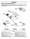
THROTTLE HANDLE ASSEMBLY
(See Fig. 2 )
• Remove the retention screw from the thrott/ehand/e.
• Slide the thrott/e hand/e ontothe rightside ofthe handle-
bar and align with the screw hole in the handlebar. The
throttle trigger should be facing away from the engine.
• Insert retention screw and tighten with hex key.
• Secure loose cable to handlebar adjacent to mounting
brackets with dip.
IMPORTANT: TWO(2) sCREWS HOLD ALL OF THE
MUFFLER PARTS TOGETHER.
• Loosen2 screwsfrom muffler screen cover withhex key.
Remove the muffler as an assembly to become familiar
with it's disassembly/reassembly sequence.
• Hold muffler with the screws up.
• Removethe fo!lowing: mufflergasket, mufflerbody,rein-
forcement plate; baffle plate, and distance pipes.
• Turn overthe muffler cover with the screws down.
• Remove 2 screwsand raise muffler screen cover.
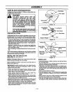
• Positionspark arrestorscreen between themuffler cover
and the muffler screen cover. Align holesand reinsert 2
8cl_ev_s_
"' * Turn overmuffler cover with screws up.
• Reinstall in the following Order:. distance pipes, baffle
plate and reinforcement plate. Seat mufflerbody over
muffler cover and snap them together. Reinstall muffler
gasket.
• Insert2 screws in cylinderand tighten securely
(60-80 Ib-in).
• Replacethe cylindercover making sure the mufflerguard
interlockswiththecrank case assembly. Insert4 screws,
• and tightensecurely.
CylinderCover/MufflerGuard
_X".'_ _\;. Cylinder
Muffler
Crank B_
Case
Reinforcement Spark
Plate Arrestor
Screen
Distance /
Muffler Muffler
Cover Screen
Plate Cover
Figure 3
-6-