


i i
OPERATION
STOPPING YOUR ENGINE
• Move engine switch to the =STOP" position.
• If engine does not stop, move the choke lever upward
(Full Choke).
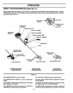
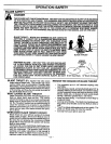
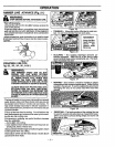
SHOULDER HARNESS (Fig. 16 )
_ WARNING:
WHEN WORKING WITH A BRUsHWACKER
IT SHOULD ALWAYS BE HOOKED TO A
SHOULDER HARNESS. IF NOT, YOU CAN-
NOT CONTROL THE BRUSHWACKER
SAFELY WHICH CAN CAUSE INJURY TO
YOURSELF OR OTHERS.
• Place harness on the shoulders with the latch on the
i
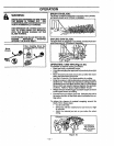
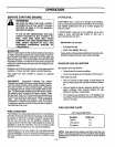
BLADE TRANSPORT/STORAGE COVER
(Fig. 17 )
• Turn offtheengine before installingthe blade transport/
storage cover over the blades.
• AttachthebladetransporVstoragecoverovertheblade,
which may be or_or offof the unit.
Brush Tri-Blade Saw Blade
chest, the Danger Signon,theback;,andthe_ook.on:the;_:
dght thigh..The h0ok::ShOul_
above your knee, or 6"(15cm) • Figure 17
Attach hook through one ofthe;susperJsion.holes.on.the ..,;i_._,_--- .. __. .. ........ ;
outer housing and adjust:the sbaulde_ hamessfor bal- • •HANDLEBAR ADau_ I MJ-Nt (t-tgure ]u )
ance so the blade or dual lihe head is level with the
ground.
Tension the side belts sothatthe weightisevenly distdl_
uted across your shoulders. A pmpedy adjusted
shoulder strap willsupport the entire weight of the unit,
freeing your arms and hands to guide and control the
cutting motion.
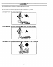
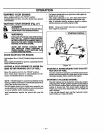
• Turn the engine offbefore adjusting handlebar.
• Put on shoulder harness and hook on the unit.
• Adjust the handlebar by slightlyunthreading the thumb
screw and rotatingthe handlebar forward or backward.
Ensure the mountingbrackets remains beWeen the ar-
rows on the handlebar.
Tighten the thumbscrew before starting the engine,
Mounting Brackets -..-.-_
Figure 18
Hook
Suspension
Hole
Figure 16
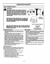
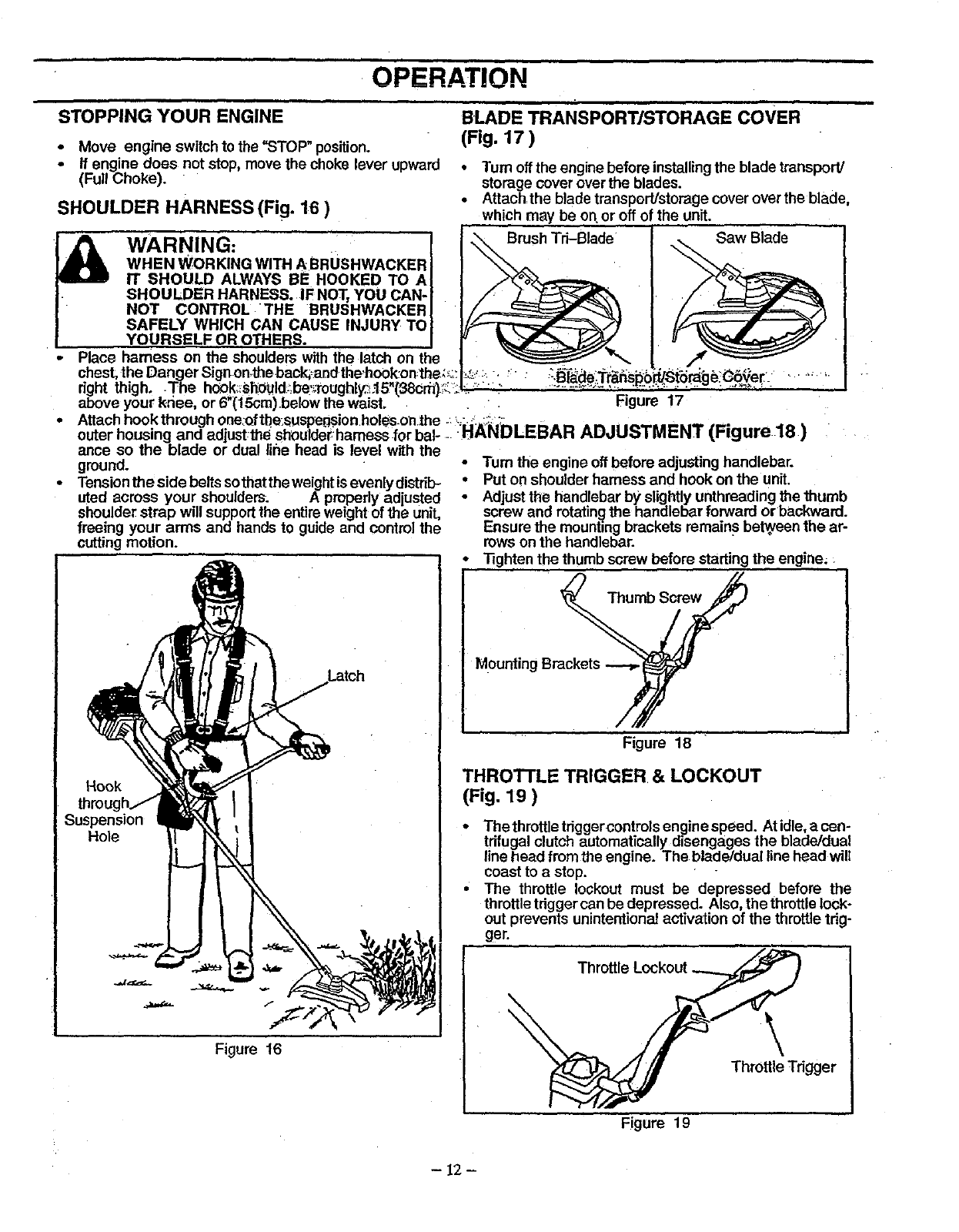
THROTTLE TRIGGER & LOCKOUT
(Fig. 19 )
• The throttle tdggercontrols engine speed. At idle,a cen-
trifugal clutch automatically disengages the blade/dual
line head from the engine. The blade/dual line head will
coastto a stop.
• The throttle lockout must be depressed before the
throttletdgger can be depressed. Also, the throttlelock-
out prevents unintentionalactivation of the throttletrig-
ger.
Throttle Lockout
\
Throttle Trigger
Figure 19
- 12-