


ASSEMBLY
CUTTING LINE HEAD
CONFIGURATION
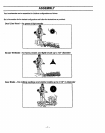
Brush and Saw Blade ConflguraUonsfollowthis section.
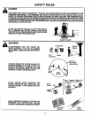
&
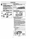
WARNING:
THE LINE LIMITER IS SHARP AND CAN
CUT YOU. BE SURE TO WEAR GLOVES
WHILE WORKING WITH THE LINE UMITER.
THE PLASTIC UNE TRIMMER SHIELD
MUST BE PROPERLY INSTALLED FOR ALL
LINE TRIMMER USAGE. THE PLASTIC
UNE TRIMMER SHIELD PROVIDES PAR-
TIAL PROTECTION FROM THE RISK OF
THROWN OBJECTS TO THE OPERATOR
AND OTHERS,
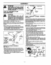
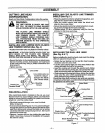
INSTALLING UNE :LIMI3_R_-ONTO PI.:ASTIC_?,__;_
LINE TRIMMER SHIELD (See Fig.4)
• Pos_on line limiteronto the plasticline trimmershield.
IMPORTANT: ALTHOUGH SCREW HOLES EXIST ON
BOTH EDGES OF THE PLASTIC LINE TRIMMER
SHIELD, MAKE SURE YOU INSTALL THE LINE UMo
rrER ON THE SIDE SHOWN IN THE ILLUSTRATION.
• Secure linelimitertotheplastic linetrimmershieldusing
the two mounting screws, lock washers, and nutsfound
in the loose parts bag using a phillips screwdriverand
8ram wrench.
• Tighten securely.
Nuts_ Une Umiter .
--,-,,,,.. / _'___,_, Line Limiter parts are
' ,,,=_,,_'"::_':rs_ locatedin a bag at-
"///'_ tashed tothe Plastic
._-- _l Line Trimmer Shield.
Plastic Line _ \y_-_- Screws
FdmmerShield
Figure 4
PRE-INSTALLATION
If the metal blade shield is installed on the unit,you must
first remove the-nut,supportflange, blade, andmetalb/ade
shield as follows before installing the plastic fine trimmer
shieldand duat line cutdng head.
• Clip blade transport/storage cover over the blade.
(Refer to figure 9)
• Toremove blade (Sea Figures 11or 14), placelockingpin
throughthe gearboxand driving disktopreventthe arbor
shaftfrom turning and remove the blade nut by turning
clockwisewith blade nut/spark plugwrench. Save parts
removed for future use.
• Remove 4 screws with hex key holdingthe metal blade
shield. Save these4 screws for installationofthe plastic
line trimmer shield.
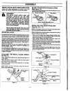
INSTALLING THE PLASTIC LINE TRIMMER
SHIELD (See Fig. 5 )
• Place the plasticline trimmershieldon the gearbox, and
align the fourscrew holes as illustmfed.
• Place the shield support plate under the shield and
align the four screw holes.
• Secure the plasticline trimmershieldusing the 4 mount-
ingscrews provided in the loose parts bag.
• Tighten evenly (70 Ib-in mimimum) using the hex key
provided in the loose parts bag.
Arbor _ -F_
Driyin_] /t!/i_ _J_ Plast_Une
.....Di 2! . / T,mme,.
- Shield
Shield Support __,, _.
Plate
Figure 5
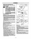
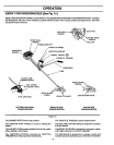
INSTALLING THE DUAL MNE HEAD
(See Fig. 6 & 7 )
Before installing the dual line head, make sure the driving
diskis in place on the gear box,
• Rotate the hex fastener on the dual line head counter-
clockwise ontothe arbor shaft.
•Tum the arbor shaftto align one of thethree holes inthe
ddving diskw_ththe hole in the gearbox.
• Insert the locking pin through the gearbox and driving
disk.This willlock the drivingdisk,and preventthe arbor
shaft from turning while you tighten the dual line head.
• While holdingthe Iockingpinin place,tightenthedual line
head onto the arbor shaft counterclockwise using the
blade nut/spark plug wrench(15-20 Ib-ft);
Should the arbor shaft continueto turnwhile you are tight-
eningthe dualline head, re-positionthe/ockingpinthrough., ,,..
the gearbox and drivingdisk.
LockingPin ArborShaft
......Plastic Line
Trimmer Shield Disk
Dual Hex Fastener
(underneath)
Figure 6
Lockin! Pir_ual Cutting Head
Plastic Line
Trimmer Shield _'< IICounterclockwis_
Blade Nut/Sl_ irk Plug
Remove Clockwis_
Wrench
Figure 7
-8-