


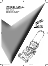

Powered Walk Behind Mower Part No. 04016067 Rev E © Copyright 6/2005
9
Rover Mowers Ltd
ABN 11 000 257 303
TM
MAINTENANCE (Continued)
Adjusting the Drive Clutches
Note: This procedure is only necessary should the drive cable adjustment not
be able to provide sufficient drive. This adjustment is to allow for wear on
the drive plates in the long term.
• Refer to the “Warning” and “Caution” notes at the beginning of the maintenance section.
CAUTION
• Remove the drive frame cover (refer to the “Removing the Drive Frame Cover” section) to expose the drive clutch
plates and other adjustments.
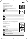
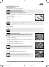
• Loosen the drive chain fully by unscrewing the chain adjuster (refer figure 25).
• Loosen the drive belt fully by unscrewing the drive belt adjuster (refer figure 26).
• Using a suitable Allen key, remove the centre fixing and thrust washer from the end of the output shaft (refer figure 27).
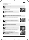
• Remove the two fixings retaining the outboard output shaft bearing housing (refer figure 28).
• Lift the outer end of the output shaft slightly and slide off the outboard output shaft bearing retainer (refer figure 29).
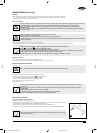
• Take note of which marking (on the boss of the inner drive plate) aligns with the end of the locking roll pin (through
the output shaft) (refer figure 30).
• Move the drive plates and actuating cam in an outboard direction until the inner drive plate is free of the roll pin
(refer figure 30).
• Rotate the inner driver plate until the roll pin aligns with the marking with ONE extra groove than that originally noted
above. Slide back to lock the drive plate to the roll pin into its new position.
• Replace the outer output shaft bearing retainer and screw down firmly in position. Apply thread locking solution to
the centre fixing.
• Replace the centre fixing and thrust washer on the end of the output shaft, apply thread locking solution to the centre
fixing and tighten firmly.
• Readjust the drive chain (refer to the “Drive Chain Adjustment” section).
• Readjust the drive belt (refer to the “Drive Belt Adjustment” section).
• Replace the drive frame cover (refer to the “Replacing Drive Frame Cover” section).
• Re-adjust the clutch cable (refer to the “Adjusting the Drive Cable” section).
• The marks on the inner drive plate boss represents positions ‘1’, ‘II’, & ‘III’. Setting ‘1’ is
generally used with a new drive plate whereas position ‘III’ is for a worn unit.
• If the drive cable adjustment is insufficient with the inner drive plate in position ‘III’ the
drive plates must be replaced.
• Clean off and apply new grease to the cams of the outboard output shaft bearing retainer
and cam lever before reassembly.
Lubricating the Drive Pawls
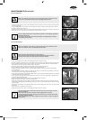
• Support the rear wheels off the ground.
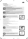
• Remove the rear hubcaps and wheel plugs (refer figure 31).
• Inspect the inside of the wheel hub through the wheel plug hole. If dirt is found, the wheel should be removed and
cleaned.
• To remove the wheel, remove the ratchet plate securing the wheel to the axle.
• Withdraw the wheel from the axle and clean out thoroughly.
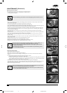
• Using clean engine oil, apply a few drops of oil to the end of the drive gear above the retaining washer and rotate the
gear to allow the oil to penetrate (refer figure 32). The gear should rotate freely, if not, repeat the above procedure.
• Replace the wheel, washer and secure with a new ratchet plate.
• If the wheel hub is clean, rotate the wheel until the drive gear is visible through the wheel plug hole.
• Using clean engine oil, apply a few drops of oil to the end of the drive gear (as above) and rotate the wheel one or two
times to allow the oil to penetrate. The wheel should rotate freely, if not repeat the procedure (refer figure 32).
• Replace the wheel plugs and the hubcaps.
• Insert a thin bladed screwdriver or similar into the slot provided between the wheel and the
hubcap to prise off the hubcap, being careful not to over bend it.
• Purchase new ratchet plates before removing the wheels as they are not reusable. Contact
your local authorized Rover service dealer.
26
27
25
28
29
31
32
30
6067 Current Artwork 10-2004.indd 5/31/2005, 8:10 AM9