


Powered Walk Behind Mower Part No. 04016067 Rev E © Copyright 6/2005
7
Rover Mowers Ltd
ABN 11 000 257 303
TM
MAINTENANCE (Continued)
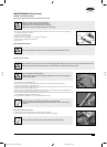
Replacing The Drive Frame Cover
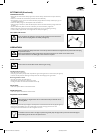
• Make sure the raised ring on the brass section of the drive cable nests into the groove of the lower drive support frame and fit the
lid accurately on top before screwing down the cover.
• Do not operate the transmission bale with the cover loose or removed as you will damage the lower drive support frame.
CAUTION
• Fit the drive cable into its retaining slot in the lower drive support frame and hold it down horizontally with one hand
(refer figure 16).
• Rotate the cover into position over the cable until it seats properly and maintain pressure on the lid above the cable.
• Screw the rear fixing above the cable down firmly.
• Screw the forward fixing down firmly.
Leave the fixings in the lid when removing or replacing.
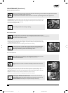
Drive Chain Lubrication
• Refer to the “Warning” and “Caution” notes at the beginning of the maintenance section.
• Do not apply excessive lubricant to the chain as it may flick off and onto the drive clutches during operation.
• Keep lubricant clear of the drive clutches.
WARNING
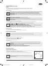
• Remove the drive frame cover (refer to the “Removing the Drive Frame Cover” section) to expose the drive chain.
• While rotating the outer clutch plate (clockwise) apply an even spread of suitable (non aerosol) chain lubricant along
the length of the chain (refer figure 17).
• Replace the drive frame cover (refer to the “Replacing the Drive Frame Cover” section).
Put the chain lubricant in a container with a long pointed spout to make application easier.
Apply a little of the lubricant on the cams between the clutch engagement lever and the
outboard output shaft bearing retainer while lubricating the chain.
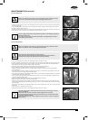
Drive Chain Adjustment
• Refer to the “Warning” and “Caution” notes at the beginning of the maintenance section.
• Keep the chain correctly tensioned to prevent damage or abnormal wear.
• Do not over tension the chain.
CAUTION
• Ensure the engine and muffler are cold before attempting to adjust the chain to prevent
burns.
WARNING
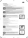
• Remove the drive frame cover (refer to the “Removing the Drive Frame Cover” section) and expose the drive chain.
• Using a long slender shaft press firmly on the chain as far from the top sprocket as possible (refer figure 18).
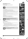
• Using a suitable Phillips head screw driver rotate the adjusting screw until the chain deflection (above) is 5mm (refer
figure 19).
• Rotate the outer clutch plate (chain), recheck chain deflection and re-adjust if necessary.
• Replace the drive frame cover (refer to the “Replacing the Drive Frame Cover” section).
• Rotate the chain adjustment screw clockwise (when looking directly at the head of the
screw) to tighten the chain tension and vice versa.
• Use a very long, or right angle single drive phillips head screw driver to better access the
chain adjusting screw.
• Check the condition of the chain joiner and sprocket and replace if necessary.
19
17
16
18
6067 Current Artwork 10-2004.indd 5/31/2005, 8:10 AM7