


10-S CHECKING, DISASSEMBLY and REASSEMBLY of the CONTROL BOX
10-5-l CHECKING OF THE CONTROL BOX
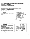
Dismount the control box from frame.
Remove the control panel and check each components and wiring.
Refer to Section 9 for the detail of checking procedure for the components in the control box.
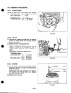
10-5-2 DISASSEMBLY
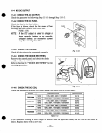
(1) Remove the control panel from the control box.
M4screw . . . . . . . . . . . . . .
6
PCS. (RGX1800, RGX2400, RGX3500)
M4 screw .-*-***.--..** 8pcs. (RGX5500)
(2) Disconnect the connectors on the wires to detach the control panel and box.
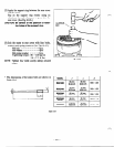
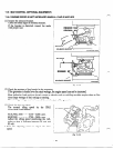
(3) Remove the condensers and diode rectifier from the control box.
(4) After disconnecting individual wires, remove the control panel components.
NOTE: DC fuse, full power switch and pilot lamp have their wires soldered. Unsolder them to
remove those parts if necessary.
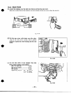
10-5-3 REASSEMBLY
(1) Install the receptacles, no-fuse breaker, fuse, terminals, switches, etc. on the control panel and wire
them.
NOTE : Circuit diagrams are shown in Section 12. Colored wires are used for easy idenfification, and
are of the correct capacity and size. Use heat-resistant type wires (permissible temperature
range 75°C or over) in the specified gauge shown in the circuit diagrams.
(2) Install condensers, and diode rectifier into the control box.
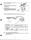
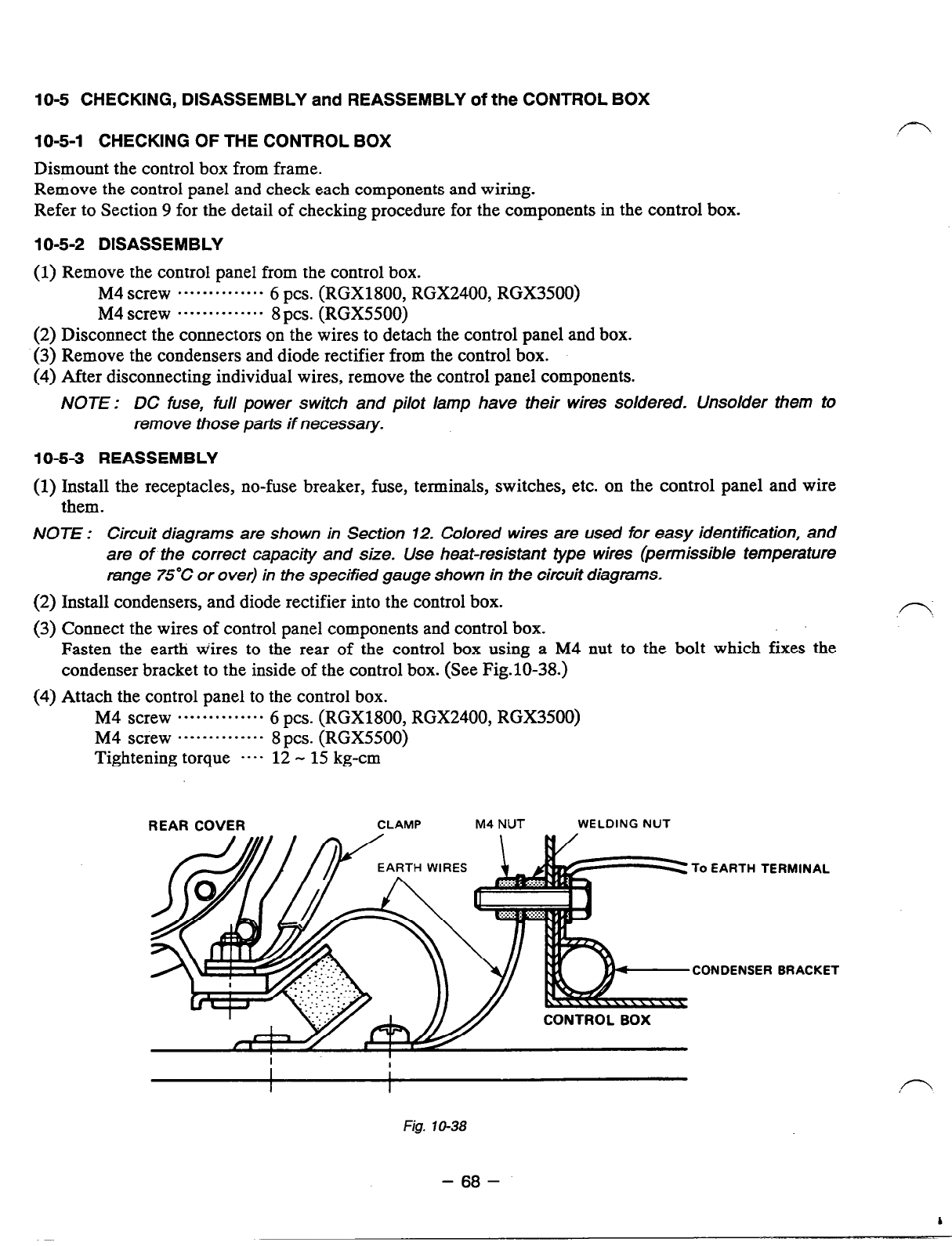
(3) Connect the wires of control panel components and control box.
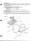
Fasten the earth w’ires to the rear of the control box using a M4 nut to the bolt which fixes the
condenser bracket to the inside of the control box. (See Fig.lO-38.)
(4) Attach the control panel to the control box.
M4 Screw . . . . . . . . . . . . . .
6
PCS. (RGX1800, RGX2400, RGX3500)
M4 screw *--.--.*..-*-. 8pcs. (RGX5500)
Tightening torque
---- 12 - 15 kg-cm
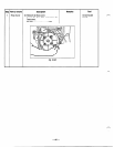
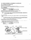
REAR COVER
CLAMP M4
NUT
WELDING NUT
EARTH WIRES
To EARTH TERMINAL
,CONDENSER BRACKET
Fig. 10-38
- 68 -