


22
B
A
C
D
E
F
G
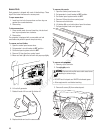
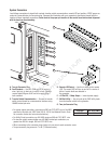
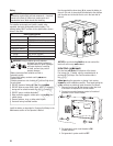
System Connectors
Low Voltage connections to signal fault contacts, transfer switch communication, remote LED and auxiliary 12VDC power are
made via a removable ten-pin connector plug. Compare this illustration with your generator to familiarize yourself with the
location of these important connections. Count down to the proper pin location on the control board since visual alignment
with the decal can bemisleading:
A - Ten-pin Connector Plug
B - Fault Contacts — Use NO, COM and NC to hook up a
siren, light, etc. to alert you in case of a fault. Contacts
reverse state (NO goes to NC and vice versa) upon a
faultcondition.
C - Transfer Switch Communication — Connect to transfer
switch control board for communication interface using
18AWG twisted pair wire.
D - Remote LED Output — Use this to hook up the remote
LED. The remote LED will turn on and off in a series of
blinks if certain faults are detected in
the generator.
E - +12 Volt DC, .5 Amp Output — Internal power supply.
F - 240 Volt Utility — Use to hook up the 240V utility leads
from the transfer switch to the generator.
G - Two-pin Connector Plug
t 'PSQPXFSPVUQVUDPOOFDUJPOVTFNJOJNVNWPMU¡$¡$XJSFPGUIF"8(
specified in this table (ref. NEC Table 310.16, 100 ft. Use National Electric Code
for correction factors and wire size calculations.):
t 'PS6UJMJUZ$JSDVJUDPOOFDUJPOVTF"8(NJOJNVNWPMU¡$¡$øXJSF
t 'PSUSBOTGFSTXJUDIDPNNVOJDBUJPOVTF"8(UXJTUFEQBJSDPOEVDUPSTOP
greater than 200 ft in length, 300 volt 75°C-90°C wire.
t 8IFODPOOFDUJOHUPUIFDPOOFDUPSQMVHTGBTUFOPOMZPOFXJSFUPFBDIDPOOFDUPSøTDSFX
t 5PSRVFDPOOFDUPSQMVHTDSFXTUPJOMC/FXUPONFUFS
Generator Wire Size (AWG)
12 kW 6
NOT
NOT
FOR
OR
and NC tand
of a
of
REPRODUCTION
UCT
UC
ook up a ook up a
ult. Contactsult. Contacts
ersa) upon
ersa) upon