


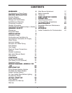
INSTALLATION
INSTALLATION
Installation Codes
Installations must follow these codes:
· Local, state, provincial, and national codes, laws,
regulations and ordinances.
· National Fuel Gas Code, ANSI Z223.1- latest edi-
tion (NFGC).
· National Electrical Code, ANSI/NFPA 70 - latest
edition (NEC).
· Standard for Controls and Safety Devices for
Automatically Fired Heaters, ANSI/ASME CSD-1,
when required (CSD-1).
· For Canada only: CAN/CGA B149 Installation
Code (B149) and C.S.A. C22. 1 C.E.C. Part 1
(C22. 1).
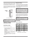
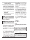
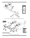
The temperature of the water in the heater can be reg-
ulated by using the temperature control. To comply
with safety regulations, the temperature control is set
at the lowest setting when shipped from the factory.
To adjust the water temperature, insert a small straight
screwdriver into the adjustment screw on the front of
temperature control and turn the wheel to the desired
setting (See Fig. 6).
CAUTION: Hotter water increases the risk of scald-
ing! There is a hot water scald potential if the
thermostat is set too high.
Fig. 6: Temperature Control
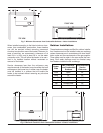
Equipment Base
The heater should be mounted on a level, structurally
sound surface. The heater is approved for installation
on a combustible surface but must NEVER be
installed on carpeting. Gas-fueled equipment installed
in enclosed parking garages must be located at least
18 in. above the floor.
CAUTION: The heater should be located in an area
where water leakage will not result in damage to the
area adjacent to the appliance or to the structure.
When such locations cannot be avoided, it is
recommended that a suitable catch pan, adequately
drained, be installed under the appliance. The pan
must not restrict air flow.
9
In addition, the heater shall be installed such that the
gas ignition system components are protected from
water (dripping, spraying, rain, etc.) during appliance
operation or service (circulator replacement, control
replacement, etc.).
WARNING: This product must be installed by a
licensed plumber or gas fitter when installed within
the Commonweatlh of Massachusetts.
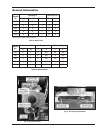
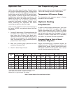
Clearances
Indoor Installations
Heater
Side
Minimum Clearance
from Combustible
Surfaces
Recommended
Service
Clearance
Floor* 0” 0”
Rear 1” 24”
Water Side 12” 24”
Other Side 1” 24”
Top 1” 1”
Front Open 24”
Vent 2” 2”
Table D: Clearances – Indoor Installations
* DO NOT install on carpeting.