27
each appliance. Adjust thermostat so appliance
will operate continuously.
e) Check the pressure at a pressure tap located 12
in. above the bottom joint of the first vertical vent
pipe. Pressure should be anywhere between -.01
to -.08 in. WC.
f) After it has been determined that each appliance
remaining connected to the common venting sys-
tem properly vents when tested as outlined above,
return doors, windows, exhaust fans, fireplace
dampers and other gas burning appliances to their
previous conditions of use.
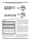
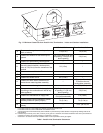
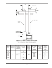
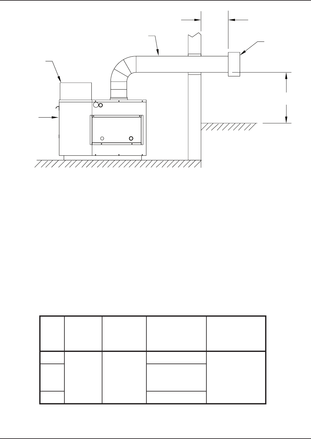
12"
MIN
FLUE EXHAUST
VENT CAP
INSULATED
EXHAUST
VENTING
12" MIN
COMBUSTION
AIR FILTER
BOILER
UNIT
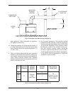
Fig. 19: Horizontal Thru-Wall Venting (Category III)
g) Any improper operation of the common venting
system should be corrected so that the installation
conforms with the latest edition of the NFGC (US)
and the B149 Installation Code (Canada). When
re-sizing any portion of the common venting sys-
tem, the common venting system should be
re-sized to approach the minimum size as deter-
mined using the appropriate tables in Appendix G
in the NFGC (US) and Appendix B of the B149
Installation Code (Canada).
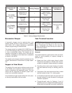
Model
No.
Appliance
Category
Certified
Venting
Material
Vent Size
(inches)
Max. Venting
Length (feet)
122
III
Stainless
Steel
(Gas Tight)
4
70
Subtract 10 ft per
elbow, maximum
three elbows
162
202
242
5
322 6
Table K: Horizontal Thru-Wall Venting (Category III)


