


37
Attach Manometers to Measure
Pressures
• Attach 24" scale manometer to the first main gas
shut-off valve pressure tapping.
• Attach one 12" scale manometer to the manifold
gas pressure tapping. (See gas valve detail on
page 7.)
• Attach one 12" scale manometer to — Pull rubber
tube from air pressure switch off the aluminum
tubing and connect the manometer using a tee.
Turn Off Main Gas Valve;
Check the Gas Supply Pressure
1. Slowly turn on main gas shut-off valve.
2. Read the gas supply pressure from the manome-
ter; minimum supply pressure is 5” W.C.,
recommended supply is 7” W.C. for natural gas
(minimum 11” W.C. for LP gas).
3. If pressure is > 14" W.C., turn off the valve.
4. Check if the service regulator is installed and/or
adjust the service regulator.
Start-Up
Blower Adjustment
1. Disconnect fan pressure switch tubing at plenum
and connect manometer using a tee.
2. Close all manual firing valves.
3. Turn power on.
4. Check manometers attached to fan pressure
switch. The readings should be :
0.5 ± 0.1 in. WC for models 102 and 122.
0.7 ± 0.1 in. WC for models 202, 242, 322.
If not, adjust the air shutter on the blower to attain
the correct value. (See air shutter adjustment
page 7).
5. Turn power off.
WARNING: If Common - Ground is > 1 VAC,
STOP: Contact electrician to correct ground failure.
Failure to do this may burn out 120V-24V
transformer, or may cause other safety control
damage or failure.
6. Reconnect fan pressure switch tubing to original
position.
Main Burner Adjustment
1. Turn off unit.
2. Open manual firing valve.
3. Turn on the unit, wait 15 seconds, and the igniter
should glow. Sight glass to check igniter at both
ends of the heater. Gas valve should be open after
45 seconds.
4. If burner does not light on first trial. It will retry, up
to 3 times.
5. Main burner ignition – check manifold gas pres-
sure at gas valve manifold pressure tap. (See gas
valve detail page 7) This should read 3.5 ± 0.1 in.
WC for natural gas or 10.5 ± 0.1 in. WC for LP gas.
6. If the pressure reading differs by more than ± 0.1
in. WC. Remove manifold adjustment screw cover
off the pressure regulator on the gas valve, adjust
main burner manifold pressure. Replace the man-
ifold adjustment screw cap on the gas valve.
Your Hi Delta is tuned in!
Safety Inspection
• Replace main gas manifold adjustment screw cap.
• Check all thermostats and high limit settings.
• During the following safety checks leave manome-
ters hooked up, check and record.
• If other gas fired equipment are in the room and on
same gas main check all pressures on the Hi Delta
with all other equipment running.
• Check thermostats for ON/OFF operation.
• Check High limits for ON/OFF operation.
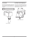
• While in operation, check flow switch operation
• Check the low gas pressure switches (For proper
adjustment, if available, use the attached
manometers to set pressure. The scales on the
switch are approximate only); Low gas pressure
switch must be set at 5 in. WC for natural gas and
10 in. WC for LP gas.
• High gas pressure switch (optional) at 1 in. WC
above manifold pressure.
• Insert ignition control lockout tests as safety
check.