


26
Natural Draft Vertical Venting
System Installation
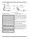
Natural draft venting uses the natural buoyancy of the
heated flue products to create a thermal driving head
that expels the exhaust gases from the flue. The neg-
ative draft must be within the range of -.01 in. to -.08
in. WC as measured 12 in. from the appliance flue out-
let to ensure proper operation. Vent material must be
listed by a nationally recognized test agency.
The maximum and minimum venting length for
Category I appliance shall be determined per the lat-
est edition of the NFGC (U.S.) or B149 Installation
Code (Canada).
The diameter of vent flue pipe should be sized accord-
ing to Part 11 of the latest edition of the NFGC (U.S.)
and part 7 and appendix B of the B149 Installation
Code (Canada). The minimum flue pipe diameter for
conventional negative draft venting using double-wall
B type vent is 4” for 122, 5” for 162, 202 and 242, 6”
for 322.
The connection from the appliance vent to the stack
must be as direct as possible and shall be the same
diameter as, or larger than the vent outlet. The hori-
zontal breaching of a vent must have an upward slope
of not less than 1/4 inch per linear foot from the heater
to the vent terminal. The horizontal portions of the vent
shall also be supported for the design and weight of
the material employed to maintain clearances and to
prevent physical damage or separation of joints.
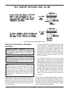
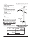
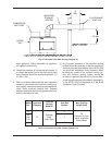
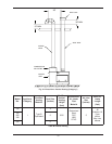
Natural Draft Vertical Vent
Termination
The vent terminal should be vertical and should termi-
nate outside the building at least two (2) feet above the
highest point of the roof that is within 10 feet. The vent
cap should have a minimum clearance of four (4) feet
horizontally from and in no case above or below
(unless a four (4) foot horizontal distance is main-
tained) electric meters, gas meters, regulators and
relief equipment. The distance of the vent terminal
from adjacent public walkways, adjacent buildings,
open windows and building openings must be consis-
tent with the NFGC, or in Canada, the B149
Installation Code for Gas Burning Appliances and
Equipment. Gas vents supported only by flashing and
extended above the roof more than five feet should be
securely guyed or braced to withstand snow and wind
loads.
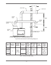
Natural Draft Vertical Venting with
Common Venting System, Category I
Appliance Only
Manifolds that connect more than one heater to a com-
mon chimney must be sized to handle the combined
load. Consult available guides for proper sizing of the
manifold and the chimney. At no time should the area
of the vent be less than the area of the largest heater
exhaust outlet.
Common venting systems may be too large when an
existing unit is removed. At the time of removal of an
existing appliance, the following steps must be fol-
lowed with each appliance remaining connected to the
common venting system placed in operation, while the
other appliances remaining connected to the common
venting system are not in operation.
a) Seal any unused opening in the common venting
system.
b) Visually inspect the venting system for proper size
and horizontal pitch and determine there is no
blockage or restriction, leakage, corrosion or other
unsafe condition.
c) Insofar as is practical, close all building doors and
windows and all doors between the space in which
the appliances remaining connected to the com-
mon venting system are located and other spaces
of the building. Turn on clothes dryers and any
appliance not connected to the common vent sys-
tem. Turn on any exhaust fans, such as range
hoods and bathroom exhausts, so they will oper-
ate at maximum speed. Do not operate summer
exhaust fan. Close fireplace dampers.
d) Place in operation the appliances being inspected.
Follow the manufacturers instructions for lighting
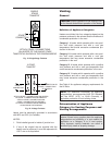
NOTE: Vent Adapter will have to be used to connect
B vent to the unit.
CAUTION: Listed vent cap terminal must be used
and sized adequately to evacuate the flue products
from the heaters.
WARNING: Vent connectors serving appliances
vented by natural draft shall not be connected into
any portion of mechanical draft systems operating
under a positive pressure.
CAUTION: Vent connectors for natural draft
venting systems must be type “B” vent or better.