


12
WARNING: Do not use one permanent opening
method if the equipment room is under negative
pressure conditions or the equipment is common
vented with other gas-fired appliances.
1. Ventilation of the space occupied by the heater
shall be provided by an opening(s) for ventilation
air at the highest practical point communicating
with outdoors. The total cross-sectional area of
such an opening(s) shall be at least 10% of the
area required in (2) and (3), but in no case shall
the cross-sectional area be less than 10 sq. in.
(6500 sq. mm.).
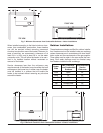
2. For heaters using a barometric damper in the vent
system, and when air supply is provided by natu-
ral air flow from the outdoors for natural draft,
partial fan assisted, fan-assisted or power draft-
assisted burners, there shall be a permanent air
supply opening(s) having a cross section area of
not less than 1 sq. in. per 7000 BTUH (310 sq. mm
per kW) up to and including 1 million BTUH, plus
1 sq. in. per 14000 BTUH (155 sq. mm per kW) in
excess of 1 million BTUH. This opening(s) shall be
either located at or ducted to a point neither more
CAUTION: All combustion air must be drawn from
the air outside of the building; the mechanical equip-
ment room must communicate directly with the
outdoors.
Canadian Installations
Water Piping
General
The heater should be located so that any water leaks
will not cause damage to the adjacent area or struc-
tures.
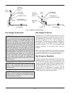
Relief Valve Piping
than 18 in. (450 mm) nor less than 6 in. (150 mm)
above the floor level. The duct can also "Goose
Neck" through the roof. The duct is preferred
straight down 18” from floor, but do not place near
piping. This air supply opening requirement shall
be in addition to the air opening for ventilation air
required in (1).
3. For heaters not using a barometric damper in the
vent system, and when air supply is provided by
natural air flow from outdoors for a power burner
and there is no draft regulator, drafthood or similar
flue gas dilution device installed in the same
space, in addition to the opening for ventilation air
required in (1), there shall be a permanent air sup-
ply opening(s) having a total cross-sectional area
of not less than 1 sq. in. for each 30,000 BTUH (70
sq. mm per kW) of total rated input of the burn-
er(s), and the location of the opening(s) shall not
interfere with the intended purpose of the open-
ing(s) for ventilation air referred to (1). This
opening(s) can be ducted to a point neither more
than 18 in. (450 mm) nor less than 6 in. (150 mm)
above the floor level. The duct can also "Goose
Neck" through the roof. The duct is preferred to be
straight down 18” from floor, but do not place near
piping.
4. Refer to the latest version of the B149 for addition-
al information.
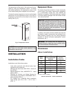
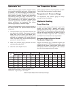
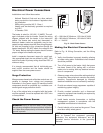
CAUTION: This heater requires forced water
circulation when the burner is operating. See Table F
and Table G for minimum and maximum flow rates
and water pump selection. The pump must be
interlocked with the heater to prevent heater
operation without water circulation.
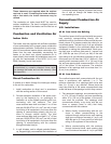
WARNING: Pressure relief valve discharge piping
must be piped near the floor and close to a drain to
eliminate the potential of severe burns. Do not pipe
to any area where freezing could occur. Refer to
local codes.
Btu per hr (11 cm
2
per kW) of total input rating
of all equipment in the enclosure.
2. One permanent opening, commencing within 12
in. (30 cm) of the top of the enclosure, shall be
permitted where the equipment has clearances of
at least 1 in. (2.5 cm) from the sides and back and
6 in. (16 cm) from the front of the appliance. The
opening shall directly communicate with the out-
doors or shall communicate through a vertical or
horizontal duct to the outdoors or spaces (crawl or
attic) that freely communicate with the outdoors,
and shall have a minimum free area of:
a. 1 sq in. per 3000 Btu per hr (7 cm
2
per kW) of
the total input rating of all equipment located in
the enclosure, and
b. Not less than the sum of the areas of all vent
connectors in the confined space.