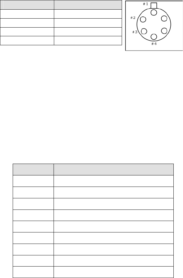
3. Make sure that power supply is switched OFF and connect it to POWER connector on
the SD3. Connect the line cord provided with the SD3 to the power supply and the AC
line. The power supply will operate with line voltages between 100 and 250 volts AC
50/60 Hz and provides +5 volts DC for the SD3 control logic and +24 volts DC for the
motor drives.
Pin # Description
1 +5V
2 GND
3 GND
4 +24V
Table 2: Power Input Pin Arrangement:
4. Connect the SD3 to a computer.
Computer: Use one of the two-supplied computer cables:
RS-232 IBM PC or compatible 9-pin female (DB9S) connector to 9-pin male
connector ( DB9P).
USB USB Cable Type A to Type B.
NOTE: If neither of these cables is compatible with your system, consult Princeton
Instruments for a custom cable. If you have facilities for constructing a custom cable,
use the RS232 pin arrangement shown in Table 3.
Pin # Description
1 open
2 RD data from SD3 to computer
3 TD data from computer to SD3
4 open
5 ground
6 open
7 RTS
8 CTS
9 open
Table 3: RS232 Computer Interface Pin Arrangement:
5. For RS232 communication, set up the terminal or RS232 computer port as follows:
9600 baud, 8 data bits, no parity, 1 start bit, 1 stop bit.
5


