


2.4 Pumping System Mounting:
The instrument is now ready for mounting to a pumping system. The VM-502 and Pumping
Port Size drawings (pages 18 and 19, respectively) show the location and dimensions of a
pumping port in the instrument base. The instrument may be supported by the pumping port or
by the three pads provided.
---------------------------------------------------------------------------------------------------------------------------
CAUTION: DO NOT APPLY EXCESS PRESSURE BETWEEN THE PUMPING PORT AND
THE THREE PADS PROVIDED ON THE BASE OF THE INSTRUMENT!
---------------------------------------------------------------------------------------------------------------------------
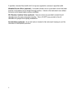
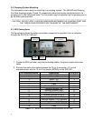
2.5 SD3 Connections:
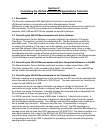
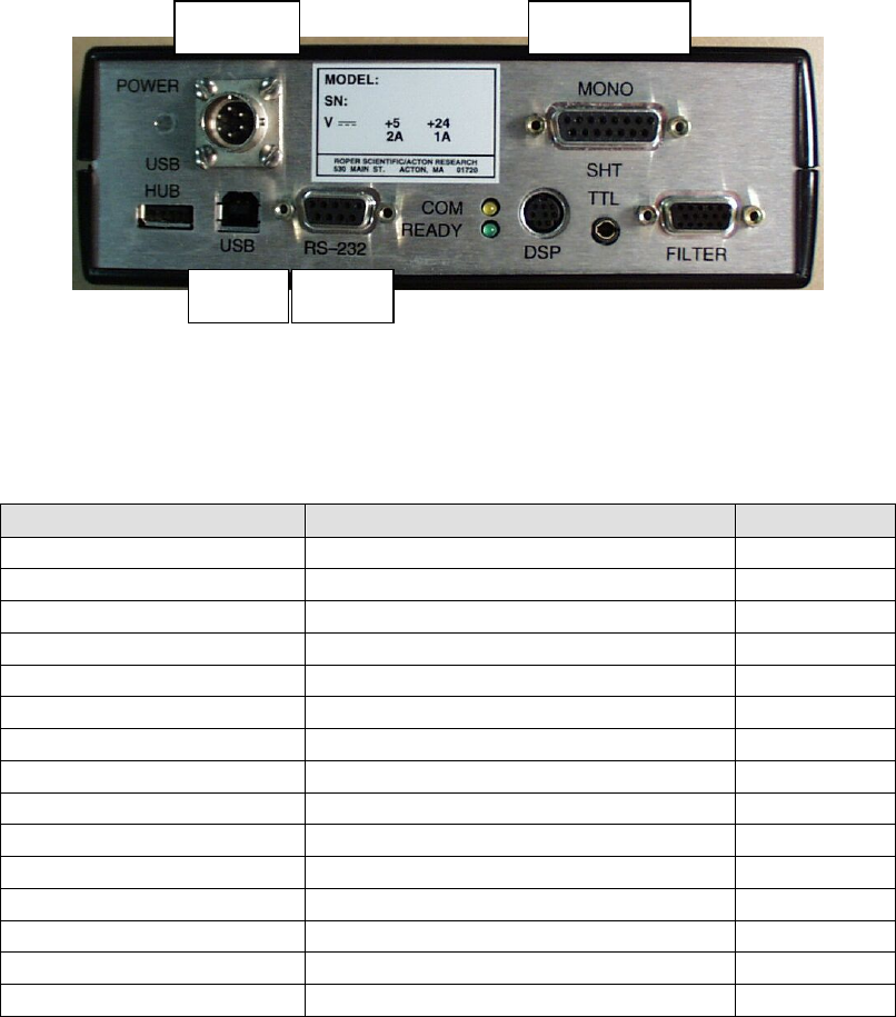
The figure below shows the cable connections necessary for operation from a computer
through the RS-232 or USB port.
Power
Connection
Monochromator
Connection
USB
Interface
RS-232
Interface
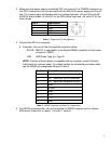
1. Locate the SD3 controller, two interconnecting cables, the power supply and power
cable.
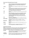
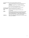
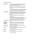
2. Connect the motor drive cable between the 15 pin D connector (J1) on the
monochromator and the 15 pin D connector (MONO) on the SD3-502.
Pin #-Monochromator Description Pin #-SD3
1 Motor – A1 1
2 Motor – A2 2
3 Motor – B1 3
4 Motor – B2 4
5 Open 5
6 Shield–(Controller Only) 6
7 Interrupt Module +5V 7
8 Interrupt Module GND 8
9 Interrupt Module 1 LED K 9
10 Interrupt Module 2 LED K 10
11 Interrupt Module 1 LED A 11
12 Interrupt Module 1 OUT WORM 12
13 Interrupt Module 2 LED A 13
14 Interrupt Module 2 OUT MOTOR 14
15 Open
Table 1: J1 - Motor Drive Connector at Monochromator and SD3-502
4