


8
Section III.
Instrument
Operation
3.1 Bilateral Slit Assemblies:
1. Slit
Width: The slit width of each bilateral slit assembly is adjustable from 0.005 millimeters
to 3 millimeters (5 to 3,000 micrometers) by a micrometer knob located on the slit housing.
The micrometer knob is graduated in 0.01 millimeter (10 micrometer) increments.
One counterclockwise revolution of the micrometer knob increases the slit width 0.25
millimeters (250 micrometers). For maximum reproducibility, the slit width should be set in
a counterclockwise direction (increasing slit widths) each time it is changed.
The micrometer knob should not be rotated below a reading 0.00 or above a reading of
3.00. A micrometer setting of less than 0.005 millimeters (5 micrometers) cannot be used,
because a stop is provided to prevent the slit jaws from touching each other.
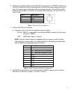
2. Slit
Height: The slit height is controlled by a pair of horizontal baffles located in the slit
housing, and must be set up prior to mounting a pair of graduated blocks, located in the slit
housing. The graduations on the blocks are 1 mm apart, with the center graduation being
the widest. To adjust the baffles, loosen the screws at each end of the horizontal baffles,
loosen the screws at each end of the horizontal baffle and set the baffles to 1/2 the total
desired slit height above and below the center graduation.
3. Optional Adapters are available for use with Princeton Instruments CCD Cameras. Cameras
are available that will allow operation down to the VM-502 lower wavelength limit of 3 0 nm.
NOTE: In most optical systems, resolution deteriorates with increasing slit height;
therefore, if maximum resolution is required, slits of one to four millimeters should be used.
3.2 Fixed Width Slit Assemblies: (optional)
Slit apertures 1 cm high and with a fixed width are provided. The width of each slit is marked
on each fixed slit assembly. The fixed slit assemblies are removable from the slit housing and
are precisely aligned to a master slit for each interchange and precise alignment.
3.3 Grating and Holder Assembly:
The grating holder assembly is kinematically mounted onto a rotary table in the instrument
vacuum chamber. Therefore, after initial alignment, the assembly can be removed and
replaced without alignment.
To remove the grating holder assembly from the instrument, the following procedure is
recommended:
1. Make sure that the instrument is at atmospheric pressure.
2. Remove the instrument cover by rotating the two cover knobs counterclockwise until the
screws are loose. Remove the cover.
---------------------------------------------------------------------------------------------------------------------
CAUTION: THE GRATING IS NOW EXPOSED--DO NOT TOUCH, TALK, OR
BREATHE ON THE GRATING!
---------------------------------------------------------------------------------------------------------------------