


9
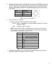
3. Place the shipping grating cover supplied over the face of the grating. Loosen the one
8-32 clamp screw in the base of the grating assembly and remove the
complete grating holder assembly.
Reverse the procedure when reinstalling the grating assembly.
NOTE: To ensure proper positioning, make sure that the grating assembly is properly seated
before tightening the 8-32 clamp screw. The clamp screw should be tightened the same
torque to ensure proper positioning.
------------------------------------------------------------------------------------------------------------------------------
CAUTION: If the instrument has a movable diverter mirror, make sure that the diverter mirror
and the control knob on the cover align before replacing the instrument cover. Refer to
Section 3.5 for more information.
------------------------------------------------------------------------------------------------------------------------------
3.4 Air Inlet Valve: (optional)
An air inlet valve is supplied to bring the main instrument chamber to atmospheric pressure,
and is located in the instrument housing. The valve is open when the handle is in line with the
valve body, and closed when the handle is at 90º to the valve body.
---------------------------------------------------------------------------------------------------------
CAUTION: Make sure that the vacuum system is in the proper mode
before opening air inlet valve!
---------------------------------------------------------------------------------------------------------
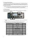
3.5 Movable Diverter Mirror: (optional)
A movable diverter mirror diverts the beam from the “V” slit position to the straight through slit
position. A knob on the instrument cover indexes the mirror to either the “S” or “V” position.
The “V” position, positions the mirror out of the beam, and the “S” position diverts the beam to
the straight through slit position. To change the mirror position, gently rotate the knob to the
desired “S” or “V” position; a click will be heard and felt when the mirror indexes into position.
NOTE: When the instrument cover is replaced, make sure that the diverter mirror and its
control knob are set to the same “S” or “V” position for proper engagement of the mirror and
knob control arm.
3.6 Slit Chamber Isolation Valves: (optional)
Vacuum valves are located in the slit housing to isolate the slit chamber from the main
instrument chamber. A valve control knob is located on the top of each slit housing. The valve
is open when the knob is in line with the optical beam and closed when the knob is in line with
the silver dot on the slit housing. (approximately 80 degrees to the beam).
---------------------------------------------------------------------------------------------------------------------
CAUTION: Never vent the main instrument chamber with the slit chamber isolation valves
closed. Never open the slit chamber isolation valve with the main instrument chamber under
vacuum and the slit chambers at atmospheric pressure. When the main instrument chamber is
under vacuum, the slit chambers must be evacuated to 200 Torr or less before the slit
chamber isolation valves can be opened.
---------------------------------------------------------------------------------------------------------------------