15
UseonlytheLowKickbackreplacement
chain specified in the listof availablere-
placement parts. The chain must com-
ply with kickback requirements of ANSI
B175.1 when tested with this s aw. See
your authorized service dealer to re-
place and sharpen individual cutters on
your chain.
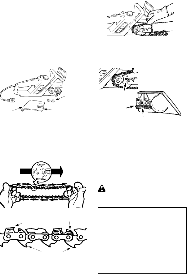
TO REPLACE CHAIN:
1. Disconnect the chain saw from the
power source.
2. Remove bar clamp nuts.
3. Remove bar clamp and old c hain.
Bar Clamp
Nuts
Adjusting Screw
Bar
Clamp
4. Turn the adjusting screw counter-
clockwise to move the adjusting pin
almost as far as it will go to the rear.
Do not remove the adjusting screw
from the bar clamp.
5. Carefullyremovethenew chainfrom
thepackage. Holdchainwithcutters
facing as s hown.
CUTTERS MUST F ACE IN
DIRECTION OF ROTATION
Tip of
Bar
Cutters
Depth Gauge
Drive Links
6. Place chainaroundthe sprocketand
fit the drive links into the guide bar
groove and then into the teeth of the
sprocket in the tip of the guide bar.
7. Hold the guide bar against the saw
frame and install the bar clamp. Be
sure adjusting pin is in the adjusting
pin hole in the bar.
Inside view of
Bar Clamp
Adjusting
screw
Adjusting pin
Adjus ting pin hole
8. Secure the guide bar and bar clamp
with the bar c lamp nuts; tighten
finger tight only.
CAUTIO N: If saw chain is installed ba ck-
war ds, the saw will vibr ate excessively
and will not cut wood.
CHAIN ADJ UST MENT
See
CHECK CHAIN TENS ION in the MAI N-
TENA NCE
section.
CUSTOMER SERVICEABLE PARTS
WARNING: Use of any other ac-
cessory or attachment might present a
risk of injury to the operator.
REPLACEMENT PART PART NO.
Hex Nut s 530015917
Oil Cap 530053072
Bar Adjust ing Screw 530016265
Bar Adjust ing Pi n 530053068
File (5/32″ dia. ) Twin Pak 952055085
Xtra GU ARDr Chain --1 8″ 952051338
Lo--Kickr Guide Bar -- 18″ 952044418
Bar & Chai n L ubricant --1 qt. 952030203
Bar & Chai n L ubricant --1 gal. 952030204


