


6
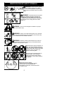
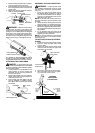
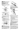
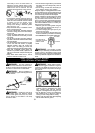
4. Position locking/releasebutton ofattach-
ment into guide recess of coupler.
5. Pushthe attachment intotheco upleruntil
the locking/release button snaps into the
primary hole.
6. Before using t he unit, tig hten the kno b se-
curely by turning clo ckwise.
Coupler
Primary Hole
Upper
Shaft
Locking/
Release
Button
Attach m ent
Guide Recess
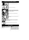
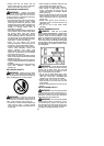
WARNING: Make su re the locking/
release button is locked in the primary hole
and the knob is s ecurely tightened before op-
erating the unit. All attachments aredesigned
to be used in the primary hole unless o ther-
wise stated in the applicable attachm ent in-
struction manual. Using the wrong holecould
lead to serious injury or damage t o the unit.
Locking /Release
Button in Primary Hole
For assembly of optional attach ments (se e list
on page 10), r efer to the ASSEMBLY secti on of
the applicab le attachment inst ruct ion manual.
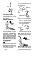
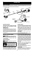
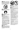
ATTACHING THE HANDLEBAR
DANGER: To avoid serious injury, t he
barrier portion of th e handlebarmust beinstalled
as shown to provide a barrier between operator
and the spinning blade.
1. Locate the decal on the handlebar. This
decal includes an arr ow. Position the
handlebar with the mounting bracket at
the end of the arrow .
2. Position the bracket cover over the han-
dlebar. Again makesure the handlebaris
at the end of the arrow .
3. Insert screws and hand tighten only. Be
sure the handlebar is installed correctly;
then, tighten each screw securely with the
hex wre nch.
Screw
Mounting Br acket
Handlebar
Bracket Cover
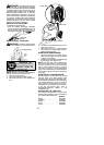
ASSEMBLY OF SHOULDER STRAP
WARNING: Proper shoulder strap
and handlebar adjustments must be made
with the engine co m pletely stopped b efore
using unit.
1. Insert your right arm and head through
the shoulder strap and allow it to rest on
your left shoulder. Make sure the danger
sign ison your back andthe hookis tothe
right side of your waist.
NOTE: A one-half twist is built in the shoul-
der strap t o allow the strap to rest flat on the
shoulder.
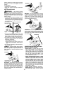
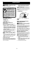
2. Adjust the strap, allowing the hook to be
about 6 inches (15 cm) below the waist .
3. F asten the strap hook to th e clamp located
between t he trigger handle and the handle-
bar cl amp base and lift the tool to the oper-
ating position.
4. Try on shoulder strap and adjust for fit
and b alance before starting the engineor
beginning a cutting operation.
NOTE: It may be necessary to relocate the
shoulder strap clam p on the shaft for proper
balancing of unit.
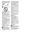
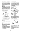
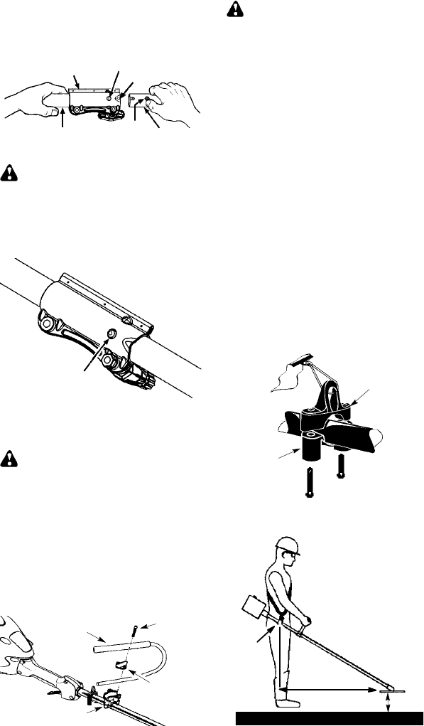
TO RELOCATE SHOULDER STRAP
CLAMP:
1. Loosen and remove both clamp screw s.
2. Place the upper shoulder st rap clamp
over the shaf t.
3. Posi tion the lower shoulder strap clamp
under the shaft and align the upper and
lower clamp screw holes.
Upper Shoulder
Strap Clamp
Screws
Lower Shoulder
Strap Clamp
4. Insert two screws into the screw holes.
5. Secu re shoulder strap clam p by tighten-
ing screws with a hex wrench.
30 inches
(76 cm)
HARNESS
ADJUSTMENT
FOR BALANCE
4 -- 12 inches
(10 -- 30 cm)
above
ground
6 inches
(15 cm)
below
waist