5
S Always keep engineon the right--hand side
of your body.
S Hold the unit firmly with both hands.
S Keep firmfooting andbalance. Donot over-
reach.
S Keep blade or trimmer head below waist
level. Do not raise engine above your waist .
S Ke ep all parts of your body awa y from blade,
trimmer head,and muf fler when e ngine is r un-
ning. A hot muf fler can cause serious burns.
S Cut from your left to your right. Cutting on
right side of the shield will throw debris
away from the operator.
S Use only in daylight or good artificial light.
S Use onl y for jobs exp lained in this manual.
TRANSPORTING AND STORAGE
S Stop the unit before carr ying.
S Keep muffler away from your body.
S Allow theengine tocool andse cure theunit
before storing or transporting it ina vehicle.
S Empty t he fuel tank before storing or trans-
porting the unit.Useupfuel leftinthe carbu-
retor by starting the engine and letting itrun
until it stops.
S Store unit so the blade or line limiter blade
cannot accidentally cause injury. The unit
can be hung by the shaft.
S Store unit out of reach of children.
WARNING: The engine exhaust
from this product contains chemicals known
totheStat eof Californiatocause c ancer,birth
defects or other reproductive har m .
SAFETY NOTICE: Expo sure to vi bra tions
through prolonged use of gasoline p owered
hand tools could cause blood vessel or nerve
damage in the fingers, hands, and joints of
people pro ne to circulation disorders or abnor-
mal swellings. Prolonged use in cold weather
has been linke d to blood ve sse l damage in
otherwise healthy p eop le. If sym ptoms occur
such as numbness, pain, loss of strength,
change in skin co lor or texture, or loss o f feeling
in the f ingers, hands, or joints, discontinue the
use of this tool a nd seek medica l attent ion. An
anti--vibra tion system does no t guarantee the
avoidance of these problems. U ser s wh o oper-
ate power tools on a continualand regul ar basis
must monitor closely their physi cal condition
and t he cond ition of this tool.
SPECIAL NOTICE: Th is unit is equipped
with a tempe rature lim iting m uf fler and spark ar-
rest ing screen which meets th e requirem ents of
Califo rnia Codes 4442 and 4 443. All U.S. forest
land and the states of Calif ornia, Idaho, Maine,
Minnesot a, New Jersey , Oregon, and W ashing-
ton requi re by law that many internal combus-
tion engines be equipped with a sp ark a rresting
screen. If yo u operate i n a locale where such
regulations exist , yo u are legally responsible for
maintaining t he opera ting co ndition of these
parts. Failure to do so is a violation of the law .
For norm al homeowner use, the muffler and
spark arrestin g scr een will not require any ser-
vice. Aft er 50 hours of u se, we r ecomm end that
your muffler be servi ced or replace d by your au-
thorized service dealer.
ASSEMB LY
CARTON CONTENTS
Check carto n contents again st the fol lowing l ist:
S Powerhead
S Lower attachment (with trimmer head
installed)
S Cupped washer
S Large nut for installing blades
S Hex wrench
S Handlebar
S Bracket cover
S Bracket cover screws (2)
S Metal blade shield
S Blade shield screws (4)
S 4--point weed blade
S Plastic shield
S Wing nut (screwed onto plastic shield)
S Shoulder strap with warning
S Container of oil
WARNING: Alwaysstopunit anddis-
connectsparkplug beforeperforming anyas-
sembly procedures.
WARNING: If received asse m bled,
repeat allsteps to ensure yourunit is properly
asse mbled and all fasteners are secure.
Examine parts for damage. Do not use dam-
aged part s.
NOTE: If you need assistance or find parts
missing or damaged, call 1-800-554-6723.
It is normal for t he fuel filt er to rattle in the
empty fuel tank.
Finding fuel or oilresidueon muf fler isnormal
due to carburetor adjustments and testing
done by the m anufacturer .
TOOLS REQUIRED
S Hex wrench (provided)
S Adjust able wrench
S Phillips screwdriver
INSTALLING BRUSHCUTTER
ATTACHMENT
CAUTION: When installing brushcutter at-
tachment, place the unit on a flat surface for
stability.
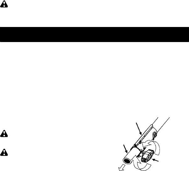
1. Loosen the coupler by turning the knob
counterclockwise.
Shipping
protector
Coupler
Knob
LOOSEN
TIGHTEN
2. Removeshipping protector from c oupler.
3. Rem ove the shaft cap from thebrush cutter
attachment (if present).


