


9
S Do not run engine at high speed while not
removing snow.
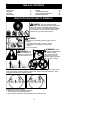
S Be atten tive when using the snowthrower,
and stay alert for holes in the terrain and
other hidden hazards.
S Make sure the rotor will spin freely before
attaching the snowthrower to the power-
head.
S Ifthe rotor will notrotate freely duetofrozen
ice, thaw the unit before thoroughly before
attempting to operate under power.
S Keep the rotor clear of debris.
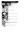
S Do not throw snow near other people. The
snow thr ower could propel small objects at
high speed causing injury .
S After striking a foreign object, stop the en-
gine, disconnect spark plugand inspect the
snowt hrower for damage and r epair if nec-
essa ry befor e restar ting unit.
S Never operate the snowt hrower near glass
enclosures, automobiles and trucks.
S Never attempt to use t hesnowthrower ona
roof.
S Never operat e the snowthrower near win-
dow wells, dropoffs, etc.
S Never discharge snow onto public roads or
near moving traffic.
S Clear snow from slopes by going up and
down; never across. Use caution when
changing directions.Neverclear snowfrom
steep slopes.
S Letsnowthrower runfor a few minutes after
clearing snow so moving parts do not
freeze.
S Look behind and use care when backing
up. Exercise c autionto avoidslippingorfal-
ling, especially when operating in reverse.
S Know how to stop quickl y.
ASSEMB LY
WARNING: If r eceived assembled,
repeat allsteps to ensure yourunit is properly
asse mbled and all fasteners are secure.
Examine parts for dam age. Do not use dam-
aged part s.
NOTE: If you need assi stance or find parts
missing or damaged, call 1-800-554-6723.
It is normal for the fuel filter to rattle in the
empty fuel tank.
Finding fuel or oilresidueon muf fler isnormal
due to carbur etor adjust m ents and testing
done by the manufacturer.
INSTALLING TRIMMER OR EDGER
ATTACHMENTS
CAUTION: Wh en removi ng or inst alling at-
tach ments, place the unit on a flat surface for
stab ility.
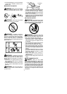
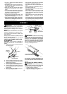
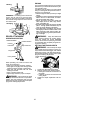
1. Loosen the coupler by turning the kn ob
counterclockwise.
Shipping
protector
Coupler
Knob
LOOSEN
TIGHTE N
2. Remove shipping protector from coupler.
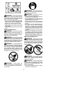
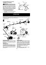
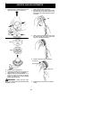
3. Remove the shaft cap from the trimmer
attachment (if present).
4. Position locking/ release button o fattach-
ment into guide recess of coupler.
5. Push theattachment intothe co upleruntil
the locking/release button snaps into the
primary hole.
6. Before usingtheunit,tightenthe knobse-
curely by turning clockwise.
Coupler
Primary Hole
Upper
Shaft
Locking/
Release
Button
Attachment
Guide Recess
WARNING: Make sure the locking/
release button is locked in the primary hole
and the knob is s ecurely tightened before op-
erating the unit. All atta chme nts are des igned
to be used in the p rimary hole unless otherwise
stat ed in the applicabl e attachment instruction
manual. Usingthe wrong h ole could l ead toseri-
ous inj ury or d am age to the u nit.
Locking/Release
Button in Primary Hole
For assembly of optional attachments (see
list on page 12) , refer to t he ASSEMBLYsec-
tion of the applicable attach ment instruct ion
manual.
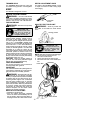
ADJUSTING THE ASSIST HANDLE
WARNING: When adjusting the assi st
handle, besu re i t r emains above the safety label
and below the m ark or arrow on the shaft.
1. Loosen w ing nut on handle.
2. Rotate the handle on the shaft to an up-
right position; retighten wing nut.