


12
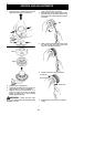
4. Pull starter rope handle sharply until en-
gine starts and runs.
5. Allow unit to run for 10--15 seconds, then
fully squeeze the throttle trigge r to disen-
gage the starting system.
STARTING A WARM ENGINE
1. Squeeze and hold the throttle trigger .
Keep throttle trigger fully squeezed until
engine runs smoothly.
2. Pull starter rope sharply while squeezing
throttle trigger until engine runs.
NOTE: Normally , t he warm starti ng procedure
can be used within 5--10minu tes after the unit i s
turned off. If t he unit sits for more than 10 mi n-
utes without being ra n, it wi ll be necessary to
star t the unit b y follow ing the steps under
STARTINGACOLDENGINEorfollowingthe
star ting instru ction ste ps shown on the unit.
START ING A FLOODED ENGINE
Flooded engines can be start ed by placing
the start lever to the RUN position. Fully
squeeze thrott le trigger. Pull the starter han-
dle repeatedly whilesqueezingthrottletrigger
until engine starts and runs. This could re-
quire pulling the st arter handle many times,
depending on how badly the unit is flooded.
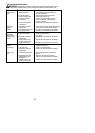
If the unit st ill doesn’t st art, refer to
TROUBLESHOOTING TABLE or call
1-800-554-6723.
OPERATING THE COUPLER
This mode l is equipped with a coupler which
enables optional attachments to be installed.
The optional attachments are:
MODEL:
Cultivato r PP2000T...................
Blower PP3000B.....................
Brush cutter PP4000C.................
Pruner PP5000P.....................
Pruner PP5500P.....................
WARNING: Alwaysstopunit anddis-
connect s park plug beforeremoving orinstal-
ling attachments.
REMOVING LINE TRIMMER ATTAC H-
MENT, EDGER ATTACHMENT OR
OTHER OPTIONAL ATTAC HMENTS
CAUTION:
When removing or installing at-
tachments, place the unit on aflat surface for
stability.
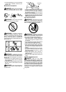
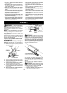
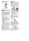
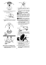
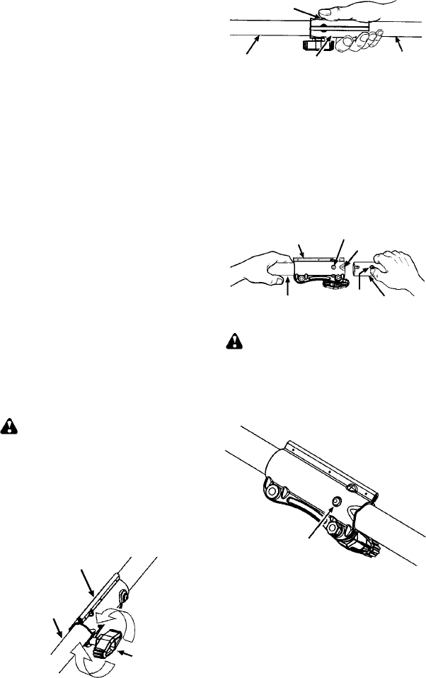
1. Loosen the coupler by turning the kn ob
counterclockwise.
Attach m ent
Coupler
Knob
LOOSEN
TIGHTEN
2. Press a nd hold t he locking/ release butt on.
Locking/Release
Button
Coupler
Upper Shaft
Attachment
3. While securely holding the engine and
upper shaft, pull the attachment straight
out of the coupler.
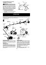
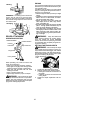
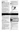
INSTALLING OPTIONAL ATTACH -
MENTS
1. Remove the shaft cap from the attach-
ment (if present).
2. Position locking/release button ofattach-
ment into guide recess of coupler.
3. Push theattachmentinto the c oupleruntil
the locking/release button snaps into the
primary hole .
4. Before usingtheunit, tightenthe knobse-
curely by turning clockwise.
Coupler
Primary Hole
Upper
Shaft
Locking/
Release
Button
Attachment
Guide Recess
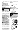
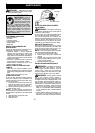
WARNING: Make sure the locking/
release button is locked in the primary hole
and the knob is s ecurely tightened before op-
erating the unit. All atta chme nts are des igned
to be used in the p rimary hole unless otherwise
stat ed in the applicabl e attachment instruction
manual. Usingthe wrong h ole could l ead toseri-
ous inj ury or d am age to the u nit.
Locking/Release
Button in Primary Hole
OPE RATING INS TRUCTIONS
It i s recommended that t he engine not be
operated for longer than 1 minute at full
throttle.