


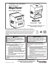

MegaTherm Commercial Pool Heating Boiler
Page 9
IMPORTANT NOTE: The pool filter pump and
boiler must be electrically interlocked so the boiler
cannot come on unless the pump is running and there
is full flow in the filter piping where the boiler is
connected. If the pool filter pump operation is
intermittent the boiler must be shut off prior to pump
shutdown. See paragraph heading Auxiliary Time
Clock Wiring below. If the backwash operation is
manual the boiler must be shut off manually during
backwashing.
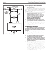
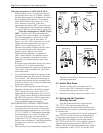
Auxiliary Time Clock Wiring:
If a time clock is used to control the filter pump
operation, a separate switch or relay must be used to
shut off the boiler at least
15 minutes before the filter
pump is shut off. Wire the switch or relay (often called
the Fireman Switch) to the terminals shown in the
wiring diagram as “Field Interlock.”
4. All field installed electrical safety devices and all
field installed controllers (valve end switches,
draft switches, relays, timers) can be connected
to the boiler control to the terminals shown in the
wiring diagram designated “Field Interlock.”
5. Field location of the temperature sensor is
described in Section 2.8.
Where the boiler is installed with a draft fan refer
to the fan manufacturer's wiring diagram. The draft
switch should be wired across the field interlock
terminals in the boiler control panel.
2.6 General Piping Instructions
In addition to the bypass valve “B” and outlet
valve “A” shown in Figure 10, an inlet valve “C”
should be provided so that the heater can be readily
isolated for service. All valves should be butterfly or
ball style,
not gate valves. For spas application see
Section 3.9.
Since heater outlet temperatures can reach
150°F (66°C) in some cases, copper or CPVC are
recommended materials for heater connection piping.
PVC material may be used for the inlet valve and the
piping upstream of it.
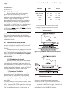
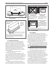
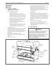
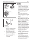
Figure 9. Pressure Relief Valve Location.
When pipe, fittings, grids or any other element of
the filter system are made of plastic materials, they
may be damaged by the momentary "back siphoning"
of hot water from the heater when the filter pump
stops running.
The pressure relief valve installed in the tapped
opening provided in the outlet header (see Figure 9),
must be piped, but not connected, to a drain or floor
sink. The drain pipe must be the same size as the valve
outlet and must pitch downward from the valve.
Where no special setting of the relief valve is ordered,
the factory will furnish a 75 psi setting.
The pressure relief valve lever must be tripped at
least once a year to insure that waterways are clean.
When manually operating lever, water will discharge
through the drain line. Precautions must be taken to
avoid contact with hot water and water damage.
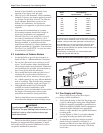
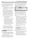
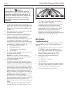
2.7 Boiler By-Pass Piping
All MT series boilers, 500-1825 models, must be
installed with bypass piping. Please use Figure 10 as
your guide to plumb the bypass. For spas see Section
3.9.
The diverter valve in the main line, shown in
dashed line in Figure 11, is optional and may be
needed only if the distance to the heater is over 15'.
Call the Service Department at 800-900-9276,
extension 5406 for assistance.
All models are supplied with integral pumps,
These pumps are sized for the pressure drop through
the heat exchanger, 30 feet of piping and through the
bypass piping as shown in Figure 10.
Any deviations from the arrangement shown
may reduce flow, hinder performance, and will void
the warranty.
2½ inch NPT piping is shown, however, models
500I-1430I and models 500E-1010E may be installed
using 2 inch NPT piping.
All models must be installed in the primary-
secondary arrangement shown. The boiler loop piping
must tee into the filter loop piping with the inlet and
outlet connection spaced a maximum of 18" (450mm)
apart (see Figure 10).
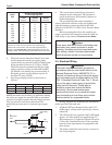
To insure that pool inlet water does not exceed
104°F, the filter pump loop must circulate at the
minimum flow rates shown in Table 4.
The outlet valve “A” and the bypass valve “B”
must have a provision for locking the handles in place
(or removing them) after the temperature rise and inlet
temperature adjustments have been made.
Boiler Model Minimum Filter Pump Flow Rate
500-850 90 GPM
1010-1200 110 GPM
1430 140 GPM
1670-1825 180 GPM
Table 4. Minimum Flow to Supply Heater Loop.