


MegaTherm Commercial Pool Heating Boiler
Page 15
should check the water temperature with an
accurate thermometer; spa or hot tub
thermostats may err in regulating water
temperatures by as much as four degrees
Fahrenheit (2.2°C).
e. Persons with a medical history of heart
disease, circulatory problems, diabetes or
blood pressure problems should obtain their
physician's advice before using spas or hot
tubs.
f. Persons taking medications which induce
drowsiness, such as tranquilizers,
antihistamines or anticoagulants, should not
use spas or hot tubs.
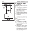
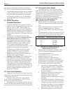
Figure 15. Pilot Safety Relay.
SECTION 4.
Maintenance
1. Lubricate the pump seal every 6 months with
½ oz. of SAE 30 non-detergent oil. Slowly add
to pump oil cup located on top of the bearing
bracket.
2. At start-up and every six (6) months thereafter,
the pilot and main burner flame should be
observed for proper performance (see Figure 16).
See attached lighting and shut-down instructions
for proper pilot flame pattern. If flame has the
appearance of "sooting" tips, check for debris
near orifices and call the Pentair Water
commercial Pool and Spa technical support (see
page 2).
3. Inspect the venting system for obstruction,
leakage and corrosion at least once each year.
4. Keep heater area clear and free from combustible
material, gasoline and other flammable vapors
and liquids (see Table 1 for minimum
clearances).
5. Be certain all combustion air and ventilation
openings in the room are unobstructed.
6. Check for fouling on the external surfaces of the
heat exchanger every six months. (NOTE: after
installation and first start-up, check the heat
exchanger for fouling after the following periods
of operation: 24 hours, 7 days, 30 days, 90 days
and once every six months thereafter.)
Fouling on the external surfaces of the heat
exchanger is caused by incomplete combustion
and is a sign of combustion air and/or venting
problems. As soon as any fouling is observed,
the cause of the fouling should be corrected (see
Section 5, Troubleshooting Guide). The heat
exchanger can be checked with a flashlight by
locating a mirror under the burners. An alternate
method is to remove the venting and top panels
as necessary to inspect the heat exchanger from
above. Also check the vent system for defects at
this time. (If cleaning is required, shut off all
electrical and gas supply to the heater.)
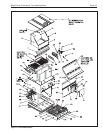
7. To expose the heat exchanger:
Indoor Models: Remove the flue pipe, top of
unit, rear upper jacket, flue collector rear panel
and heat exchanger baffles.
Outdoor Models: Remove vent top assembly,
rear upper jacket, flue collector rear panel and
heat exchanger baffles.
8. To remove all burners:
It is usually more convenient to remove the
burner tray assembly. Disconnect sensor wire,
ignition cable (or thermocouple generator) and
pilot gas line. Disconnect manifold inlet union(s).
Remove the four (4) retaining screws. Grasp the
manifold pipe and slide out the burner tray.
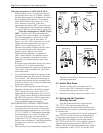
Pilot Relay Manual
Reset Switch
(Standing Pilot Systems)
Figure 14. Manual Gas Valves.
Pilot Valve
Main Gas Valve
Pilot Valve
Main Gas Valve
ON POSITION
OFF POSITION