


Pentair Water Commercial Pool and Spa
Page 8
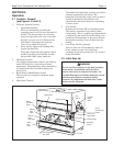
6. The correct burner manifold gas pressure is
stamped on the rating plate. The regulator is
preset at the factory and normally requires no
further adjustment.
The gas manifold and control assembly is
factory tested and conforms to the safe lighting and
other performance criteria specified in the latest
editions of ANSI Z21.13.CSA4.9 Low Pressure Boiler
Standard.
Before operating the boiler, the complete gas
supply system and all connections must be tested for
leaks using a soap solution. Do not use raw flame.
Caution
Since some leak test solutions (including soap
and water) may cause corrosion or stress
cracking, the piping must be rinsed with water
after testing, unless it has been determined
that the leak test solution is noncorrosive.
2.5 Electrical Wiring
WARNING
The boiler must be electrically grounded in
accordance with the most recent edition of the
National Electrical Code, ANSI/NFPA 70. In
Canada, all electrical wiring to the boiler should
be in accordance with the latest edition of CSA
C22.1 Canadian Electrical Code, Part 1. Do not
rely on the gas or water piping to ground the
metal parts of the boiler. Plastic pipe or
dielectric unions often isolate the boiler
electrically. Service and maintenance
personnel who work on or around the heater
may be standing on wet floors and could be
electrocuted by an ungrounded boiler.
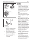
Wiring diagrams are included in the information
packet provided with each unit.
1. All Model MT pool heating boilers need 115V
60Hz supply voltage unless specifically ordered
otherwise.
2. The 1825 models are supplied with 3/4 HP pump
motors. All other models are supplied with 1/2
HP pump motors. Consult the National Electrical
Code or the Canadian Electrical Code regarding
branch circuit requirements for equipment with
these motors.
3. The boilers should be wired exactly as shown in
the wiring diagram.
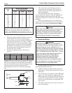
Distance from Gas Meter
Boiler or Last Stage Regulator
Size
0-100' 100-200' 200-300'
0-30.5m 30.5-61m 61-91.4m
500 1½" 2" 2"
600 1½" 2" 2½"
715 2" 2" 2½"
850 2" 2½" 2½"
1010 2" 2½" 3"
1200 2½" 3" 3"
1430 2½" 3" 3"
1670 2½" 3" 3
1825 2½" 3" 3½"
NOTE: These figures are for Natural Gas (.65 Sp. Gr.), and are
based on 1/2" water column pressure drop. Check supply
pressure with a manometer, and local code requirements for
variations. For Propane Gas, reduce pipe diamter one size. An
average number of tees and elbows have been taken into account.
Table 3. Gas Piping Sizes.
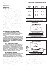
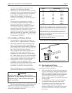
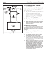
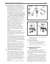
Figure 8. Sediment Trap Installation.
To
Equipment
Inlet
Gas Supply
Inlet
Tee
Fitting
3" (76mm) Min.
Cap
Nipple
4. The boiler and its individual shutoff valve must
be disconnected from the gas supply piping
system during any pressure testing of that system
at test pressures in excess of 1/2 psig (3.5kPa).
The boiler must be isolated from the gas supply
piping system by closing its individual manual
gas shutoff valve during any pressure testing of
the piping system at test pressures equal to or
less than 1/2 psig (3.5kPa).
5. Provide gas supply pressure to the heater as
follows:
Natural Gas Propane Gas
In. W.C.
kPa
In. W.C.
kPa
Max. 10
2.5
14
3.4
Min. 6.5
1.6
11
2.7
NOTE: the heater and all other gas appliances sharing
the boiler gas supply line must be firing at maximum
capacity to properly measure the inlet supply pressure.
Low gas pressure could be an indication of an
undersized gas meter and /or obstructed gas supply
line.