


MegaTherm Commercial Pool Heating Boiler
Page 17
1. Symptom: heater is pounding, knocking or emitting steam from relief valve
Possible Cause What to Do
A. Low or no water flow A. Is the heater wired into the filter pump circuit so that the heater cannot fire
(most likely). unless the pump is running?
Check to see that all valves in system are open to be sure that water can
circulate through the heater.
Check pool filter, clean if clogged.
Examine heater pump for clogged or frozen impeller.
Check flow switch for proper operation and range setting.
B. Debris from system piping B. Remove header covers. Examine all tubes and waterways. Clean out tubes.
is blocking tubes. Use new gaskets when reassembling.
C. Scale has formed in tubes C. Clean tubes with tube cleaning kit. Determine hardness. Check water flow, and
from high mineral content. clean pool filter.
2. Symptom: heater will not fire
A. Heater not getting power. A. Check to see that power switch is "ON." Use testing device to trace power to
heater power source. Check fuse and secondary voltage in heater control.
B. Operating or safety control has B. Turn off power. Check continuity across terminals of each operating and safety
opened circuit to electric gas valve. control switch up to the electric gas valve. Replace defective control.
C. Pilot flame is out. C. Relight pilot per instruction.
D. Manual reset device has tripped. D. Reset pilot safety and all manual reset safety switches. Follow instructions for
start-up.
E. No gas pressure to burners. E. Trace gas line to service shutoff cock. If service cock is open, trace gas line to
meter. If no pressure is present at meter, call for public utility service. If gas is
present in heater inlet, check pressures in following sequence: (1) downstream
from pressure regulator; (2) downstream from electric gas valve. Replace or
adjust as necessary.
F. Electric gas valve operator is F. Disconnect wiring harness at gas valve terminals. Check continuity of actuator
burned out or shorted. coil. If open circuit or short is indicated, replace coil or operator.
G. Pump does not run. G. Operate in manual. Check power to pump from relay, Check that pump/motor is
free to rotate. Replace relay or motor as necessary.
H. Pump runs, but flow switch H. Check continuity across flow switch. Inspect paddle for proper movement.
not closing. Adjust flow range setting.
I. Field interlock open. I. Jumper terminals and isolate problem in other equipment.
3. Symptom: pressure relief valve leaking intermittently or steadily
A. Faulty relief valve. A. Replace with a new relief valve with proper setting (see rating plate).
4. Symptom: soot in flueways or in tubes, or noxious fumes from bad combustion
A. Combustion air supply to heater A. Check air supply opening. Look for debris in screen or louvre which covers
room is inadequate. combustion air opening, or for objects blocking the opening.
B. Stack or vent is blocked or restrictive. B. Look for blocked stack and excessive number of elbows in stack or excessive
length of horizontal runs.
C. Severe downdraft is causing C. Check for (1) proper vent cap on stack; (2) adequate height of stack above
spillage of flue products into room. roof; (3) equipment exhausting air from inside of building; and (4) proper
installation of draft diverter.
D. Gas pressure to burners is excessive. D. Check gas pressure with manometer, and adjust with heater firing at full rate.
E. Heater not fitted for the fuel supplied. E. See nameplate for correct fuel.
F. Heater installed at high altitude F. Installations at altitudes in excess of 2000 ft. above sea level are subject to
without proper derating. jurisdiction of the local inspection authorities. Check orifice size, contact your
dealer or factory for proper size.
5. Symptom: water dripping in firebox
A. Tube in heat exchanger has A. Tube failure is almost always caused by scale formation in the tube, or
overheated and ruptured. inadequate water flow through the heater.
B. Heater is condensing from low B. Check bypass valve adjustment.
inlet temperature.
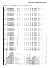
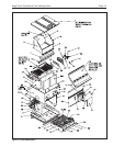
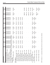
SECTION 6. PARTS