


MACRO range installation manual. Issue 6
Page 6
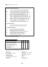
GENERAL SPECIFICATIONS
MIXER AMPLIFIERS M1008 M2508
M1008/D M2508/D
Input channels 8 8
Input channel level & response dependent upon input modules fitted
Treble & Bass adjustment ± 12dB @ 100Hz & 10kHz ref.1kHz
Power output (Watts RMS contin.) 100 250
Current sinks 250mA maximum, each channel module
Auxiliary DC output nominally +24V. 1A fused.
Mixer facility level 775mV nominal. 0dBV
Power amplifier input 775mV , 0dBV @ 10k ohms
Power amplifier power freq. resp. -3dB @ 20Hz & 20kHz ref. 1kHz, low imp
-3dB @ 20Hz & 15kHz ref. 1kHz, 100V
Loudspeaker matching 100V/50V line balanced
AC mains supply input 240V 50-60Hz +5% -15%
24V DC supply input (22-28V) 6 Amp 18 Amp
DC quiescent consumption (approx) 350mA 350mA
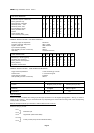
SLAVE AMPLIFIERS M100 M250
M100/D M250/D
Power output (Watts RMS contin.) 100 250
Audio input level 775mV, 0dBV @ 10k ohms
Power amplifier power freq. resp. -3dB @ 20Hz & 20kHz ref. 1kHz, low imp
-3dB @ 20Hz & 15kHz ref. 1kHz, 100V
Loudspeaker matching 100V/50V line balanced
AC mains supply input 240V 50-60Hz +5% -15%
24V DC supply input (22-28V) 6 Amp 18 Amp
DC Quiescent consumption (approx) 250mA 250mA
MIXERS M8M M8M/D
Input channels 8 8
Input level & response dependent upon input modules fitted
Treble & Bass adjustment ± 12dB @ 100Hz & 10kHz ref.1kHz
Current sinks 250mA maximum, each channel module
Auxiliary DC output nominally +24V , fused 1A
Audio output level 775mV nominal. 0dBV
AC mains input 240V 50-60Hz +5% -15%
24V DC supply input (22-28V) 250mA (module dependent)
DC quiescent consumption (approx) 150mA
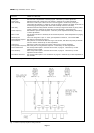
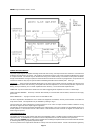
FRONT PANEL CONTROLS & INDICATORS
By design, user accessible controls are kept to a minimum to avoid inadvertent maladjustment which could render the system
ineffective.
Each input channel of a MACRO mixer or mixer-amplifier may be adjusted for gain by using the front panel controls. Should the
commissioning engineer deem it prudent, he may remove any of the complete control knob/spindle assemblies, after adjustment
is complete, simply by pulling the knob. The resulting holes may then be blanked off using the blanking plugs supplied. The
controls may be refitted at any time subsequently. Slave amplifiers to standard specification are not fitted with a front gain control.
An illuminated power switch controls AC power input (and if applicable, DC power input simultaneously).
A series of LED indicators provides a simple means of assuring the user of correct amplifier operation. A 10 segment ladder gives
an indication of output level expressed in decibels - i.e. dB relative to maximum output amplitude. Under normal programme
conditions this will fluctuate between the extreme left and extreme right segments in accordance with the amplitude of the programme
at any particular instant. No segment is illuminated when the amplifier output is zero. If the illuminated segment is predominantly
to the extreme right (maximum) then it is likely that the amplifier is being over-driven and that the resulting sound will be distorted
on peaks. Reduce the corresponding front input gain control accordingly.
A fast attack/slow decay circuit is used to drive the display so that amplitude peaks are recognised.
Two further LEDs indicate the status of the power supply in use, and of the power amplifier module where appropriate. For further
details see page 19.
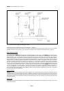
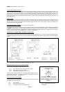
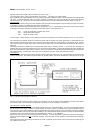
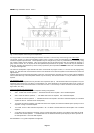
TONE CONTROL & MASTER GAIN ADJUSTMENT
Tone control facilities are provided on the line driver module, type TB.6 which is located at second right, on a mixer or mixer
amplifier when viewed from the front. Two trimmer potentiometers are located at the bottom of the module, just above the edge
connection tabs. Viewed from the front, the nearest is the bass adjustment and the furthest is the treble. Each controls a cut & lift
correction circuit with the central position of the rotator giving nominally flat response. At the extremities of rotation, the corrections
are ± 12dB at 100Hz and 10kHz respectively. Rotate controls clockwise to increase the gain at bass or treble frequencies. On