


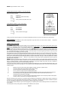
MACRO range installation manual. Issue 6
Page 14
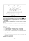
POWER AMPLIFIER MODULE
The power output stage of the amplifier including all low level drive circuitry, and output devices are contained in a module which
is bolted to the rear panel by four screws. The module is connected into circuit by push-on tab connectors facilitating easy change
of a suspect module. The module may be unbolted and swung out to enable circuitry to be worked on with power connected,
though as the heatsink is no longer coupled, the module should not be driven into a load for any length of time. Output devices are
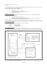
mounted on sockets so they may be replaced without dismantling the PCB from the heatsink plate. See Fig. 8
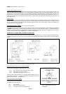
Adjustments There are three pre-settable adjustments on the power output module which are accessible from the top of the
amplifier. When received from the factory, the amplifier will have been adjusted for correct overload protection, output device
biasing, and input sensitivity, and no further adjustment will be necessary. The recommended adjustments are:
OVERLOAD: Top left of module when viewed from front: Set for triggering at full amplitude on a load of 3 x rated output.
OUTPUT DEVICE BIASING: Centre top of module: Set nominally for a total module drain of 200mA, measured via the supply
push-on tab.
INPUT SENSITIVITY: Top right of module: Set for 0.775V RMS at 1kHz.
The above adjustments necessitate the use of certain test equipment and facilities, and the precise methods are outside the
scope of this manual. The adjustments may be identified by referring to Fig. 8
The front panel error LED is energised for a minimum period of 1.5 sec. when an output overload condition is detected. During
this time, the signal drive to the output stage is suppressed.
The detection circuit and LED will remain energised for the entire duration of any such overload, and the amplifier will return to
normal operation 1.5 second after removal of the overload. Note therefore that this circuit will not register an overload until a
suitable signal is present.
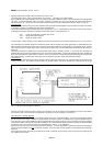
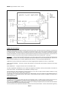
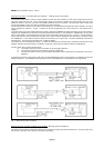
LOUDSPEAKER OUTPUT
The amplifier is designed to work primarily with 100V line loudspeaker systems. Facilities are also provided for 50V line and low
impedance loads. IT IS ESSENTIAL to provide the correct loudspeaker load for safe and distortion-free reproduction.
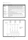
When connecting a MACRO mixer amplifier or slave amplifier onto an existing loudspeaker network, the load should be ascertained
by measuring the load by a proprietary impedance bridge
The cover provided on the output barrier terminals is a safety cover and should be retained. Access to the terminals is gained by
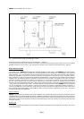
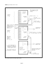
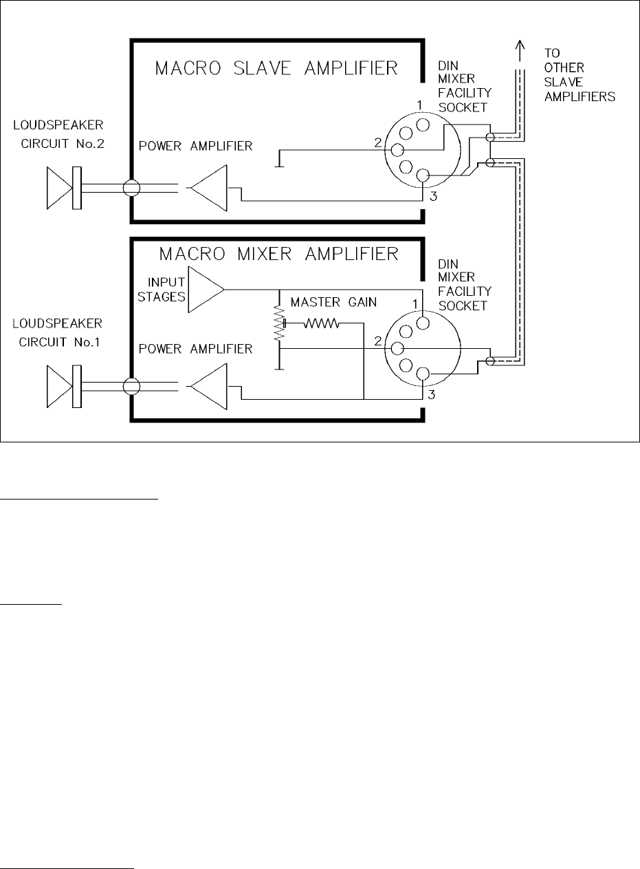
Fig. 7 Interconnection of several amplifiers