


Page 15
MACRO range installation manual. Issue 6
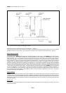
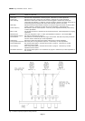
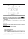
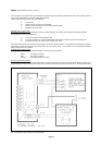
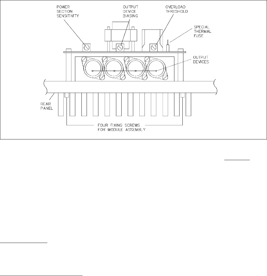
Fig. 8 Power amplifier module fixings and adjustments
removing the 4BA nut on the left and lifting that end clear of the stud. The cover may now be swung round.100V output
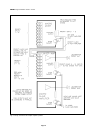
The general concept of a 100V line loudspeaker system is that a quantity of 100V line loudspeakers are connected in parallel
across the amplifier output terminals. The loudspeakers may be arranged in any order, any combination and if necessary, using
any number of feeds from the amplifier. They may be grouped onto sub-circuits which may then be controlled by switching or
group volume controls, etc., as required to suit the operational requirements of the system. Sub circuits may be dedicated to
Page-only operation and switched in by means of relays powered by the comprehensive MACRO current sinks. See APPENDIX
C for typical arrangements.
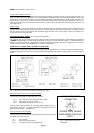
The 100V line loudspeaker output terminals will deliver conventional full program content, i.e. all music and all paging/priority
signals. For 100V line loads connect between the two outer terminals and for 50V line systems connect between the centre and
right terminals.
All three 100V line output terminals fully floating, earth-free, and centre-tapped. This latter is useful in certain critical installations
where careful balancing of the loudspeaker network may be necessary. The terminal marked CT may be earthed to chassis if
required.
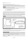
Low impedance output
Power output to the loudspeaker load may be taken at low impedance (low Z) The terminals marked A-O-B present a very low
impedance output across A-B and which is centre-tapped at O. These terminals are not specifically rated, but as a guide, the
output impedance across the A-B terminals is in the order of 2 ohms. The centre-tap is a direct connection to 0V level (chassis,
signal earth, and -24V).
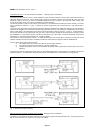
Typical loudspeaker load arrangements
The following are acceptable examples of loudspeaker loading arrangements:
A 400 x 1/2 Watt 100 Volt line speakers = 200 Watts total load to the amplifier. Use a 250 Watt amplifier
B 200 x 1 Watt 100 Volt line speakers = 200 Watts total load to the amplifier. Use a 250 Watt amplifier
C 2 x 50 Watt 100 Volt line speakers = 100 Watts total load to the amplifier: Use either a 100 Watt amplifier (or a 250 Watt
amplifier to allow for 150 Watts future development).
D 12x 5 Watt 100 Volt line speakers = 60 Watts total load to the amplifier, and therefore 40 Watts spare capacity for future
expansion if using a 100 Watt amplifier
E 10 x 5 Watt, and 6 x 2 Watt 100 Volt line speakers = 50 + 12 Watts = 62 Watts total load to the amplifier. Use a 100 Watt
amplifier.
F 4 x 60 Watt units each tapped at 30 Watts, and 20 x 4 Watt units tapped as follows: 5 @ 4 Watt, 5 @ 2 Watt and 20 @
0.5 Watt 100 Volt line speakers = 160 Watts total load and therefore 90 Watts spare capacity for future expansion or
for final adjustments. Use a 250 Watt amplifier
See APPENDIX C for typical loudspeaker arrangements.