


MACRO range installation manual. Issue 6
Page 10
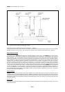
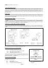
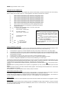
Auxiliary inputs and music modules i.e. L33, L34, E24, E25,
Standard Locking 5 pin DIN -
Pin 1 Signal input
Pin 2 Signal earth (cable audio shield)
Pin 3 Signal input
Pin 4
Priority control (except E24, E25, T35)
Pin 5
Tone generator modules i.e. T24 to T34 inclusive
Standard Locking 5 pin DIN -
Pin 1 No connection
Pin 2 No connection
Pin 3 No connection
Pin 4
Priority control & tone trigger
Pin 5
Locking 5 pin DIN connector plugs are not furnished automatically with the unit, and must be ordered as a separate item.
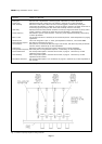
Module adjustments
Various adjustments are available on each module, dependent on type and function, etc and are shown in table 2. The general
locations are shown in APPENDIX E.
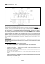
PRIORITY INPUT FACILITIES
Each MACRO amplifier (with input module facilities) can be programmed to provide up to 8 levels of signal priority which may be
arranged in a descending order access (sometimes referred to as ladder priority), or an equal access first-come-first-served
priority, or any combination of both. The modules available may be categorised into priority and passive modules, and it is the
priority modules which generate the ladder sequence. Thus if a MACRO amplifier were fitted with say five priority modules, then
obviously only a maximum of five levels of priority could be available. However, the amplifier containing the five modules may be
set up to exhibit ladder priority, for example, on inputs 1 and 2 whilst inputs 3-4-5 may be given equal access. This set-up could
now be referred to as exhibiting just 3 levels of priority.
Equal access is a form of priority whereby the first to access the priority chain locks out one (or more) other inputs for the duration.
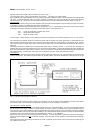
As supplied from the factory, the amplifier will exhibit a ladder sequence downwards from input No.1 as first priority. Equal access
between any modules must be between physically adjacent modules, and is instigated by depressing the small blue PCB switch
button which is located between the module input sockets on the main mother PCB. See Fig. 3. Later units utilise a DIL or Molex
type switch, which should be set to ON. There are 7 such switches, and any number may be depressed at any time to give the
required priority arrangement.
MACRO systems may be designed to include music or other non-priority facilities, and the appropriate modules will have been
specified. All such modules are passive modules and as such should occupy module sockets at the lowest end of the priority
chain. i.e. towards input No.8. Passive modules will be overridden by any priority modules in the chain, but have no facilities to
instigate any priority functions (such as current sinking) of their own.
In all cases, the priority functions of priority modules are triggered by bridging pins 4 and 5 of the DIN channel input socket. The
switching current is in the order of 2mA @ 15V. On successful access to the signal priority chain, the module circuitry will perform
certain functions:
a) Modules of equal or lower priority will be inhibited, whether of priority or passive format.
b) The audio signal path of the accessed module will be enabled
c) The channel current sink (250mA max) will be enabled
d) The any channel current sink will be enabled (250mA max)
e) The modules in immediately higher priority will be inhibited if the equal access PCB switches have been set
f) The tone sequence of a tone generator module will be started either via the module timer circuit, or
momentarily for the duration of the trigger
g) The chime sequence of a chime-microphone module will be triggered and consequently enable a CDM (chime
duration monitor) current sink to be energised (250mA max).
Should a module which is currently in an accessed mode be inhibited by the triggering of a higher priority module, all the above
functions (a) to g) where appropriate) will be lost immediately, for the duration. However the timer function will still be operative
and may re-enable the original module, if timing permits, when the higher priority is released.
Voice operated modules attempt to gain access by triggering on amplitude peaks and the resulting functions are consistent with
a) to e) above.
The audio paths of lower priority passive modules will be inhibited for the duration.
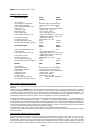
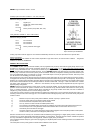
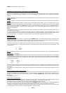
Fig. 2
Input connector pin identification
SOLDER CUPS
VIEWED FROM
INSIDE THE PLUG
BODY
5 PIN DIN
STANDARD
CONNECTOR