


MACRO range installation manual. Issue 6
Page 22
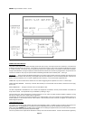
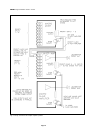
The Locking DIN pin connections are:-
Pin 1 No connection
Pin 2 out of phase audio
.775V RMS @ 10k ohms
Pin 3 in phase audio
balanced (floating)
It would normally be appropriate to interconnect two pieces of equipment using twin-screened cable. The braiding should be
earthed to one unit only. If the decision is made to use the Mustang power amplifier for earthing, then the cable clamp of the DIN
plug may be used for the purpose, without the likelihood of a hum loop.
As this is a fully floating input facility, either single or twin core screened cable may be used. This will depend upon the specification
of the equipment supplying the input signal.
The input impedance of balanced input slave amplifiers is 10k ohms.
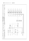
See Fig. 11 for further clarification.
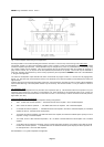
Line surveillance. Mustang product code - TB/S
The standard module fitted to a mixer or mixer-amplifier to provide line driver facilities is a TB.6 and is located second from the
right when viewed from the front. This is replaced with a TB.6S to provide the Line surveillance facility, which, in the MACRO
system is carried out by injection of an encoded supersonic tone into the audio signal path at the line driver stage. The presence
of the current which this signal induces into the loudspeaker line is subsequently monitored externally for deviation from a pre-set
level.
The amplitude of the injected signal is adjusted using the pre-set potentiometer at the top right hand corner of the TB.6S (viewed
from component side - see APPENDIX E). Turning the control clockwise will increase the level of injection. The correct factory
setting is such that 2V is the amplitude of the signal appearing across the fully loaded loudspeaker output terminals at the amplifier
rear. Useful re-adjustment of this control can be accomplished only with the aid of an oscilloscope of suitable bandwidth. The
same level applies in the case of MACRO systems incorporating mixers and slave amplification. See APPENDIX D to locate the
module, and APPENDIX E for identification of the adjustments. Adjustment of the modules treble or bass controls will not effect
the surveillance injection. Do not attempt to alter the ferrite cored inductor of the injection circuit.
The loudspeaker current monitoring function as mentioned above would be facilitated by using a MACRO SL/10 unit.
INSTALLATION
Selection of signal input cables
It is essential that input connections are made carefully, using appropriate screened cable, soldered to DIN connector plugs, and
using the appropriate terminal numbers indicated in the section describing the input modules in this manual. Unscreened telephone
type cables are NOT suitable. Either twin conductor, or single conductor types may be used depending upon the application. For
long fixed cable runs, a cable with a conventionally braided outer shield is preferable to a lap-screened type. A conductive plastic
shield type is ideal for cables which will be subject to constant flexing such as those connected directly to microphones. Failure to
meet these requirements will result in inferior performance, and at worst, damage to the amplifier.
It is not possible in this manual to be specific about the exact types of input cable for use in any particular amplification system, as
many practical factors will need to be taken into account. However, as a guide, we would recommend the following:
Balanced lines should be wired in twin, twisted core, screened cable with a conductor size of at least 0.22sq.mm., and preferably
0.5sq.mm. This is equally valid for dynamic or phantom-powered microphones, and line inputs.
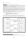
Paging microphone lines will need an extra two conductors to operate the priority circuit of the amplifier. These need not be
screened. For short runs, (up to 2 Metres), paging microphones may be connected using 4-core overall screened cable, and for
longer runs, (up to 10 Mtrs), 4-core individually screened cable. If it is necessary to run a cable over say 10 Mtrs, then there may
be some performance advantage in using a separate twin-twisted screened cable for the audio, and a separate twin unscreened
cable for the priority operate cores.
Line level cables, such as those between a tape recorder and the amplifier, which may be up to a few metres in length are less
critical and may be run using lap-screened, single or twin cable with conductors of 7/0.1mm or 7./0.2mm.
Selection of loudspeaker cables
Use of an appropriate cable for the connection of loudspeakers to the amplifier will ensure that a minimum amount of audio power
is lost during transmission to the loudspeaker network. The loss will depend upon several factors - loudspeaker loadings, size of
cable conductor, length of cable, etc.
As a general rule, for any particular loudspeaker system, the longer and the thinner the cable, the greater will be the loss. We
therefore recommend, that the system is planned such that the amplifier is as near as possible to the loudspeakers, and that the
cable used is as large as practicable.
Mineral insulated cables may be used without problem.
Either solid or flexible conductor cables may be used, or a combination of both. It would be appropriate for a heavy duty cable to
be used between the amplifier location and the general loudspeaker location - carrying the full load, and for the subsequent
loudspeakers of the network to be interconnected with thinner cable.
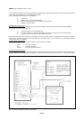
Fitting Locking DIN connectors
Signal input connections are made via a locking DIN 5-pin plug (Mustang Code 5-180). To insert:- rotate the plug until the pins line
up with the corresponding socket contacts, and push fully in. Rotate the locking ring clockwise to secure. Similar plugs used for
domestic Hi-Fi systems may be used though they are generally of inferior quality, and have a weaker cable clamp with no locking
facility.
When connecting the input cables to the locking DIN plugs, it is most important to observe the following:-