


MACRO range installation manual. Issue 6
Page 4
PAGE
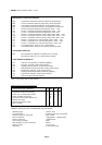
Table 1 The current range of input modules 8
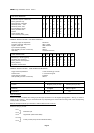
Table 2 Module adjustments and settings 11
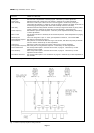
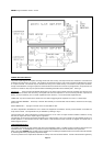
Fig. 1 Location of Treble, Bass, and Master gain controls 7
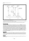
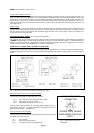
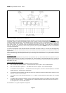
Fig. 2 Input connector pin identification 10
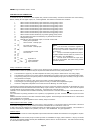
Fig. 3 Location of priority sequence setting switches 11
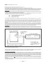
Fig. 4 Mixer facility connections for standard locking DIN connector 12
Fig. 5 Mixer facility connector pin identification 12
Fig. 6 Tape record and playback connections 13
Fig. 7 Interconnection of several amplifiers 14
Fig. 8 Power amplifier module fixings and adjustments 15
Fig. 9 Priority connections for multiple amplifier systems 18
Fig. 10 AC & DC supply connections and monitoring 19
Fig. 11 Balanced line input connections 21
Block schematic diagram APPENDIX A
Typical priority control and auxiliary arrangements APPENDIX B
Typical loudspeaker circuits APPENDIX C
Chassis layout & main component identification APPENDIX D
Locations of module adjustments and fuses APPENDIX E